Issue 2, March 1984 - Spectrolysis
| Home | Contents | KwikPik |
| SPECTROLYSIS | |||||||||||
|---|---|---|---|---|---|---|---|---|---|---|---|
| T U N I N G U P | |||||||||||
| Y O U R S P E C T R U M | |||||||||||
| How do you get the best possible picture on your television from the Spectrum's video output or even more tricky, on a monitor? Ian Beardsmore completes the picture, and at the same time introduces a forum for readers to knock around ideas. | |||||||||||
| One of the idiosyncrasies of our
beloved Spectrum, at least of the
Issue 1 and 2 models, lies in the flexibility of the display. So far as the vast
majority of Spectrum owners are concerned, their computer is not compatible with a monitor. Indeed, the
machine will not even be compatible
with some home televisions! Only the
smug owners of Issue 3s are unaffected by these problems (although they
may instead have trouble running
some early software). It's quite common to see Spectrum owners walking around Microfairs looking mystified at the sight of their computers doing the impossible: Spectrums on display being used with Toshiba televisions, and some even linked to the usually unusable Hitachi 14-inch colour portable. In the worst case of impossibility, a Spectrum may even be seen connected to a monitor. The more clued-up amongst us will be able to guess correctly that computers in this latter category have had the same modification as those Spectrums that entered schools under the 'Micros in Education' scheme. Fine for those in the know, but how about Joe User? "What the heck" you may think, "the Spectrum is a good enough bargain as it is". But if so, why the Issue 3? Probably the most frustrating aspect of all this is that published solutions are not readily forthcoming even though the 'experts' seem to make the necessary modifications with consummate ease, thus leading to even greater feelings of alienation. But relief is at hand because, in point of fact, the necessary changes are actually quite straightforward, and certainly within the capabilities of any careful Spectrum owner. Of course there is a catch. Anyone taking the lid off their Spectrum will void the guarantee! So, what you decide to do at this point is up to you. But let us assume a reckless streak has suddenly | 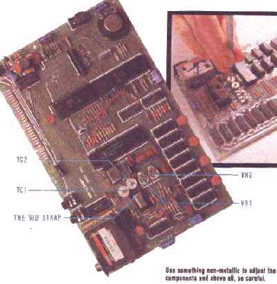
| ||||||||||
|
plunged into the otherwise calm
breast of a dedicated user. What would happen? How would our hero (or heroine) progress? First, of course, the top will have to be unscrewed, then lifted off. (This, in fact, is connected to the printed circuit board by two ribbon cables that are not long enough to allow the top to be kept completely clear of the rest of the computer. This just makes things more difficult, so take care.) Having thrown caution to the wind and voided the guarantee, the user in search of fine tuning must now locate two variable capacitors and two variable resistors. Not surprisingly (because we are dealing with the display) the area to search is around the modulator.
|
is to be used with a monitor. But more
on that later because currently we are
interested in the trimming capacitors,
TC1 and TC2, and the variable resistors, VR1 and VR2. Working from
top to bottom (see photo) this is what
they do.
First of all, beware ... when adjusting the trimming capacitors, it's best to use something non-metallic to adjust them with. A matchstick cut to shape is quite suitable. And, of course, added care should be taken anyway because all adjustments have to be made while the computer is turned on so that the results of 'tweaking' can be seen on the screen. To begin with, adjust the screw in TC2 carefully in both directions until you find the point of strongest colour even if this is still too weak. That done, try bringing up the blue/yellow | ||||||||||
| . | SPECTROLYSIS | . | ||||
|---|---|---|---|---|---|---|
| end of the colour range by adjusting
VR1. Once you've found the best
colour here, bring in VR2 and tune in
the red/green end of the colour spectrum. Essentially, what you need to
do is balance those three components
for the best picture. Again, the
watchword is care and, as a precaution, it might be wise to take note of
the pre-adjustment settings of the
three variable components. TC1 is the capacitor which controls the shimmer on the screen. Once the colour is as you want it, then this ought to be the final adjustment you make. One thing, however, is that sometimes shimmer can interfere with a viewer's perception of the other colours. It may be that further tiny adjustments of the first three will be needed, once changes have been made to TC1. Complete this juggling act and you should have your Spectrum finely tuned to a particular television.
| Below the modulator, and just to
the left of the gap between TC1 and
TC2, there is a small white line
marked 'VID'. At one end of this is a
small solder point, and at the other,
the hole of a through-the-board connection point. In fact, it's not quite as
easy as it may seem to access this line
because of the line of resistors that
stretch out below the modulator. 'VID', in fact, marks a break in the video line between the modulator and the expansion port. Obviously, as there is a break in the line, the signal cannot reach the port; therefore, all you need to do is bridge this gap. How you accomplish this feat is up to you. The simplest (and nastiest) way is to stretch a blob of solder between the solder point and the hole. A short piece of wire is better, but for more ease a longer piece can be used. Whichever way, once done you will have a composite video signal available at the port. Only two lines are involved at the port, the video line and the 0 volt line. These are placed next to each other, on the middle underside of the port. At the input end, where it enters the monitor, the video line goes to the central pin while the 0 volt line goes to the case. If you want you can adapt the UHF line supplied for use with a normal television. Otherwise, any electrical shop should have what's | needed.
All that remains now is to decide
how to take the video line from the
port. The most flexible way would be
to use a connector and motherboard.
On the other hand, it's also possible
to take the lines from another port for example, if you have the printer
always connected, this could be used
instead. However, be careful here
because with some programs, if the
printer is left connected, you get a
screen dump. Those going as far as a
monitor are, on balance, recommended to invest in a connector especially
for it.
Just drop a line to me, Ian Beardsmore, c/o Your Spectrum, 14 Rathbone Place, London W1P IDE. |
| Home | Contents | KwikPik |