Issue 5, July 1984 - Joystick Interface
| Home | Contents | KwikPik |

"Throw out the chips", urges Simon Goodwin, as he applies the age-old formula - simple is best - to his DIY joystick interface. | ||
|---|---|---|
|
You can add a standard joystick interface to the Speccy for nothing more than
the cost of some wire and a pair of plugs
and sockets. The Your Spectrum interface explained here goes one better than
Sinclair Research's one-chip Interface
2 - it uses no integrated circuits at all!
Despite this, it is compatible with a wide
range of software and not only that, but
programs which support the Interface 2
will also work with our Interface
Zero.
Like most hardware projects, Interface Zero requires you to make a few soldered connections inside your computer. This will void the warranty and could damage the computer too; don't attempt to wire up a joystick unless you are fairly confident about your soldering ability. Interface Zero is compatible with issue 1, 2 and 3 Spectrums, and it's been used on the author's Spectrum for |
over a year without problems.
Interface Zero can be used with standard Atari or Commodore joysticks, which means it can also handle similar devices such as Le Stick, Quickshot and the Competition Pro. Don't try to use |
BBC Micro or Dragon joysticks - they
generate the wrong type of signal.
Unlike Interface 2, Interface Zero doesn't provide the facility to plug ROM cartridges into your system. If you find that you need this facility, you |
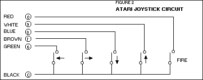
The Atari and Commodore joysticks work like one row of a key array, with four switches for each direction and another for 'Fire'. | ||
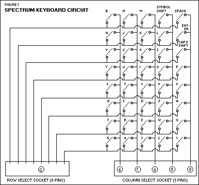
The above diagram illustrates the way the Spectrum keyboard operates via a collection of on/off switches. |
can add Interface 2 later without the
need to remove Interface Zero. Like
Interface 2, Interface Zero can allow a
pair of joysticks for two-player games.
The main snag is the number of joystick 'standards' about, and programs using one system don't always allow for the others. Consequently, a joystick connected via Interface Zero won't necessarily work with games that allow a different system, such as the Kempston (port 31) or AGF (cursor keys). However, unlike the popular Kempston system, programs that allow keys to be re-defined (such as Gold Mine from Dk'Tronics) will work fine with the interface, and it's possible to read the joystick with the normal Basic INKEY$ function. HOW THE INTERFACE WORKSInterface Zero works on a very simple principle. The Spectrum keyboard consists of a collection of on/off switches, arranged in the circuit shown in Figure 1. The physical layout is obviously different: four rows of ten keys are used, by connecting the eight rows of the circuit in pairs.The computer periodically supplies a voltage to the 'row select' socket, energising each row of the key array in turn: if a signal makes its way out of the array | |
|
(down one of the five columns) then a
key must be depressed. Since the Spectrum knows the row and column, it can
thus work out which key is pressed.
Atari and Commodore joysticks work like one row of the key array - the circuit is shown in Figure 2. A switch is used for each of four directions, with a fifth switch for the 'Fire' button. Of course, the physical arrangement of the switches in a joystick uses a cross- pattern - moving the stick simply rocks an arm on to the appropriate switch. Sinclair Research has made things extremely simple by connecting the Spectrum keys in groups of five. To connect a joystick, all you really need to do is put the five switches of a joystick in place of one of the eight groups used by the Spectrum. It soon becomes obvious that you can connect up a joystick at the same time as the keys, without electrical problems (the computer doesn't care whether it's the key or the stick switch which is closed) - either way it registers a key-press. The joystick will generate signals to duplicate the action of keys '6', '7', '8', '9' and '0' - we can't easily duplicate the cursor keys since these are split between two groups. The only problem remaining is how to connect it all up to | The next step is the tricky one. Without opening the case, turn the computer face up and slowly lift off the top section, until you can see the ribbon cables linking the keyboard to the electronics in the base. The cables are slotted into sockets on the circuit board - you will later solder the interface wires onto the |
back of these sockets.
Disconnect the keyboard by gripping the cables and pulling them evenly and squarely out of the sockets - be careful not to fold or twist the cables as you do this or you may have difficulty replacing them when you have finished. At worst you could crack the thin conductive |
If you have an Issue 2 or 3 machine you'll find the column select socket further away from the modulator - this was due to the circuit board's re-design. | ||
On Issue 1 Spectrums the row select socket is positioned just above the speaker and the column select socket below the modulator. |
strip on the back of the cable.
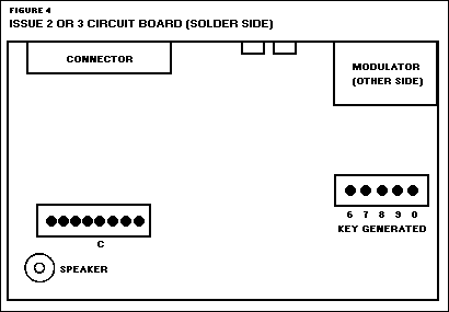
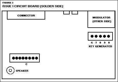
Once the cables have been unplugged, the top of the Spectrum should be completely separate from the base. Check that the cables are undamaged and then put the keyboard on one side. If the cables are cracked you may have to trim the damaged end - but be careful to cut squarely and shorten the cable as little as possible. The circuit board is held in by a single screw in its centre. Undo this screw and lift the board from the base. Turn it over so that the solder side is uppermost and the edge connector is furthest from you. Consult Figures 3 or 4 to identify the keyboard connectors. Issue 1 machines have an add-on circuit board over the edge connector, or two empty chip sockets widely spaced along the edge connector side of the board. Solder six wires to the points shown in the appropriate figure. Use thin insulated wire to avoid bending the circuit board. Multi-coloured ribbon cable is | |
the existing keyboard circuitry. The
Spectrum circuit board layout was
altered in each issue of the machine,
changing the connection points required for the joystick: Figure 3 shows
the connection points for owners of the
issue 1 Spectrum, while Figure 4
matches the layout for the issue 2 and
issue 3 machines.
OFF WITH THE LIDThe first step is to open up the computer. Disconnect everything possible, then turn the machine face down. You should be able to see five black screws on the base of the computer - one by each rubber foot and the fifth at the right- hand end of the edge connector. Remove the screws with a cross-point screwdriver. |
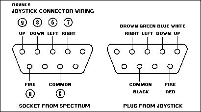
The 'standard' colour codes for the joystick plug and socket; if the colours differ for your particular 'stick, you'll have to dismantle it. | |
|
ideal; it even fits in with the Spectrum
colour scheme. The common wire,
marked 'C' in the figure, goes to the fifth
pin of the eight-way connector. Put a little solder on the end of each wire -
without frying all the insulation -
before attaching to the circuit board.
Use a soldering iron of no more than 25
watts. If a joint doesn't 'stick' at once,
remove the iron, apply fresh solder, and
try again after a few seconds.
Once all of the wires are firmly fixed, they should be taped or stuck in place with an adhesive pad on the back of the board. Then bunch the wires together so they can run out of the Spectrum below the MIC or EAR socket. Check for solder splashes on the board, and make sure that you didn't accidentally solder together any of the pins of the five-way connector. Outside the computer you'll need a nine-pin male D-type socket - the joystick plugs in to this. Figure 5 shows how you connect the number-coded wires from the computer on to the socket. These sockets are quite expensive - you could even end up paying a pound for one. An alternative, if you |
and reversing the order of the
other five wires (since keys '1' to '5' are
decoded in reverse order, as you can see
from Figure 1). Using Figure 1 as a
guide, you can decode any of the other
groups of five keys: for instance, the Q-W-E-R-T group used to control Pssst
and Cookie.
Many games written before the Interface 2 was released use a similar - but not identical - arrangement of keys for Joystick One. The Interface 2 assigns the directions 'UP' and 'DOWN' to keys '9' and '8' respectively, while programs such as Timegate, Earth Defence and 3D Tunnel use the opposite arrangement. This interface was originally built to allow Timegate to be played without the author's brain seizing up trying to manipulate the control keys chosen. If you'd particularly like to be able to play one of these early programs it may be worth reversing the connections for keys '8' and '9'. Better still, fit a switch (double pole, double throw) to select between the two arrangements - the required wiring is shown in Figure 6. A word of caution, however - since |
- probably by using too much solder on
the circuit board. If moving the joystick
has no effect at all, the common wire is
disconnected. If joystick movements
produce characters outside the group -
'6', '7', '8', '9' and'0' - you've connected the common wire to the wrong point
in the computer.
Check that the stick works reliably before re-assembling the computer, then run the joystick wire through the MIC or EAR hole, and screw down the circuit board. Position the keyboard over the base and push the ribbon cables firmly and evenly into the sockets on the top of the board, making sure that they are not twisted. Don't force the cables - when correctly positioned they should plug in securely with little resistance. Turn the computer over and replace the five screws in its base (assuming you haven't lost them). TEST PROGRAMListing 1 is a test program which allows you to steer a character around the screen with the joystick. The colour of the character changes when the Fire button is pressed. Notice that the program uses the IN command rather than INKEY$. IN allows it to detect instances when more than one key is depressed (as in diagonal movement). You can still use the relevant keys to control the character, even when the joystick is connected.
IN CONCLUSIONFollow these instructions carefully and you'll find you have added a joystick to your Spectrum for a fraction of the price most firms are asking for adaptor units. Bon chance! | ||
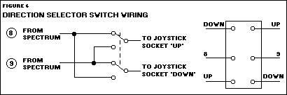
A design for games players wanting to make the most of the '8' and '9' keys. | ||||
|
can't afford or find a D-type socket, is to
use the five pins and outer 'screen' of a
DIN plug, chopping off the moulded D-type plug from the joystick and
replacing it with a more common DIN plug. At
a pinch you could use two pairs of stereo
jack connectors, with each one carrying
three of the signals.
The colour codes used in the joystick plug are also shown in Figure 5. Some sticks may use a different colour code, in which case you will have to dismantle the stick (usually a simple operation, to allow for repairs) and deduce the colours used. Commodore joysticks use pink wire for 'Fire', rather than red. We do not recommend that you solder the wires from the joystick directly on to the Spectrum circuit board. This may be the cheapest approach, but it's also the most likely to leave you with a dead computer. The joystick cable is too thick to pass easily out of the Spectrum case and, with the joystick dangling from it, you run the risk of damaging the circuit board every time you pull on the cable or move the computer. ELABORATIONSThe wiring explained so far uses the same key-assignments as Interface 2. You can even fit a second joystick by connecting the common wire from it to the right-hand pin of the eight-way connector, |
Interface Zero works by taking signals
out of the Spectrum box and down the
joystick cable, you run a slight risk that
the cable will convey external interference into the Spectrum, leading to
unreliable performance. In practice
we've not found this a problem, but it's
probably best not to extend the joystick
cable, just to be on the safe side.
TESTING TIMEIt is possible to test the interface without rebuilding the Spectrum, so long as you are careful to keep the circuit board away from conductive surfaces. Make one last check on your soldering and then connect the computer board to your TV and power supply. Plug in a joystick and leave the keyboard disconnected.As you move the stick, digits should appear on the screen. You'll find '6' and '7, correspond to left and right movement, '8' and '9' to down and up. The Fire button should produce the digit zero. If any of these values are transposed, you must have accidentally swapped the connections as you wired them up. If a single digit doesn't work the appropriate wire is not connected firmly enough. If two adjacent digits (such as '6' and '7' or '9' and '0') don't work, you've most likely accidentally connected two of the five wires together at some point | |||