8th March 2020
Having made & fitted an eccentric housing for the bearing, and changed the grub-screws from 4BA to M5, the movement is now ultra smooth and it goes round on the lightest of touches, see the video below. Bearing in mind that each of the barrels will be carrying about 14lbs of lead weight on them, that should provide more than enough power at the escape wheel to drive the pendulum as there’s virtually no resistance right the way through the motion of the clock.
Since completing this video, I have made a new escape wheel and fitted it above the third wheel (the uppermost wheel on the video). After some slight messing about with the size of the hole - they were too small for the arbour ends initially, the whole lot now moves like an angel, and I’m happy with where it stands at the moment. The next jobs are to make the end stones, drill out the plates for the pallet arbour and make the end plates for that arbour. After that it will be a matter of making the pallets & crutch, which incorporates a beat adjustment and grab pins for the pendulum.
Well, we’ve suddenly erupted into the COVID-19 epidemic, and as of last night a total lockdown in the UK has been announced. My grass has been cut just once, which is normal for mid March, but nothing else is. I suppose the upside is that it’s allowing plenty of time for clockmaking, since fishing is now banned. I was going to go today (24th March), but as of yesterday, all that is postponed for a long time to come.
On with the clock then…..
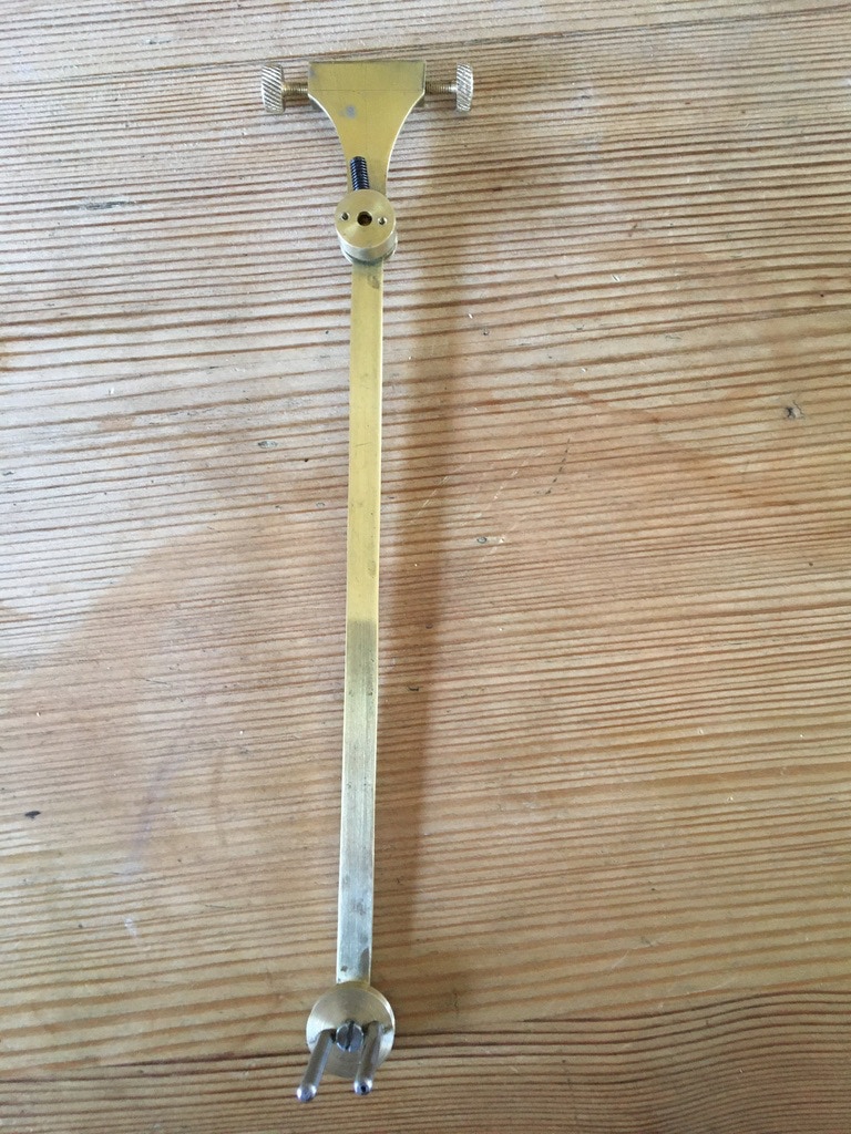
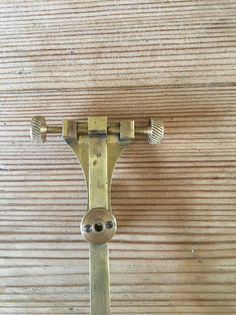
The crutch assembly is adjustable to allow the beat to be evenly regulated, and that is the purpose of the 2 screws in the crutch assembly below. The 2 pins at the bottom fit astride the pendulum rod, which provides the timing for the clock, and conversely, the crutch provides a tiny amount of power to the pendulum to keep it moving. The speed of its beats is set entirely by the pendulums length, and were it frictionless it would beat indefinitely. This being the real world however, there is friction from the air and the crutch, hence the necessity to feed it a tiny bit of power on each beat. This picture is the crutch finished, but not properly cleaned up ready to be fitted to the clock. The marks come from soldering the blocks at the top of the assembly.
Now, to get the power from the escape wheel (the pointy one at the top of the gear train), the pallets nibs that allow the teeth to be released every second have a cunningly designed edge to them, so that as they release the gear, the pointy bits at the end of the wheel push the pallet aside, providing the power to be transferred back to the pendulum. The engineering for this is horribly complex & accurate, and to make the pallet nib edges, I needed to cut a part circle of tool steel at a tangent to the inside, and outside of an imaginary 1.29” circle. Complicated enough? Well, then each pallet nib needs to be cut away from the circle, cleaned & polished, then hardened,
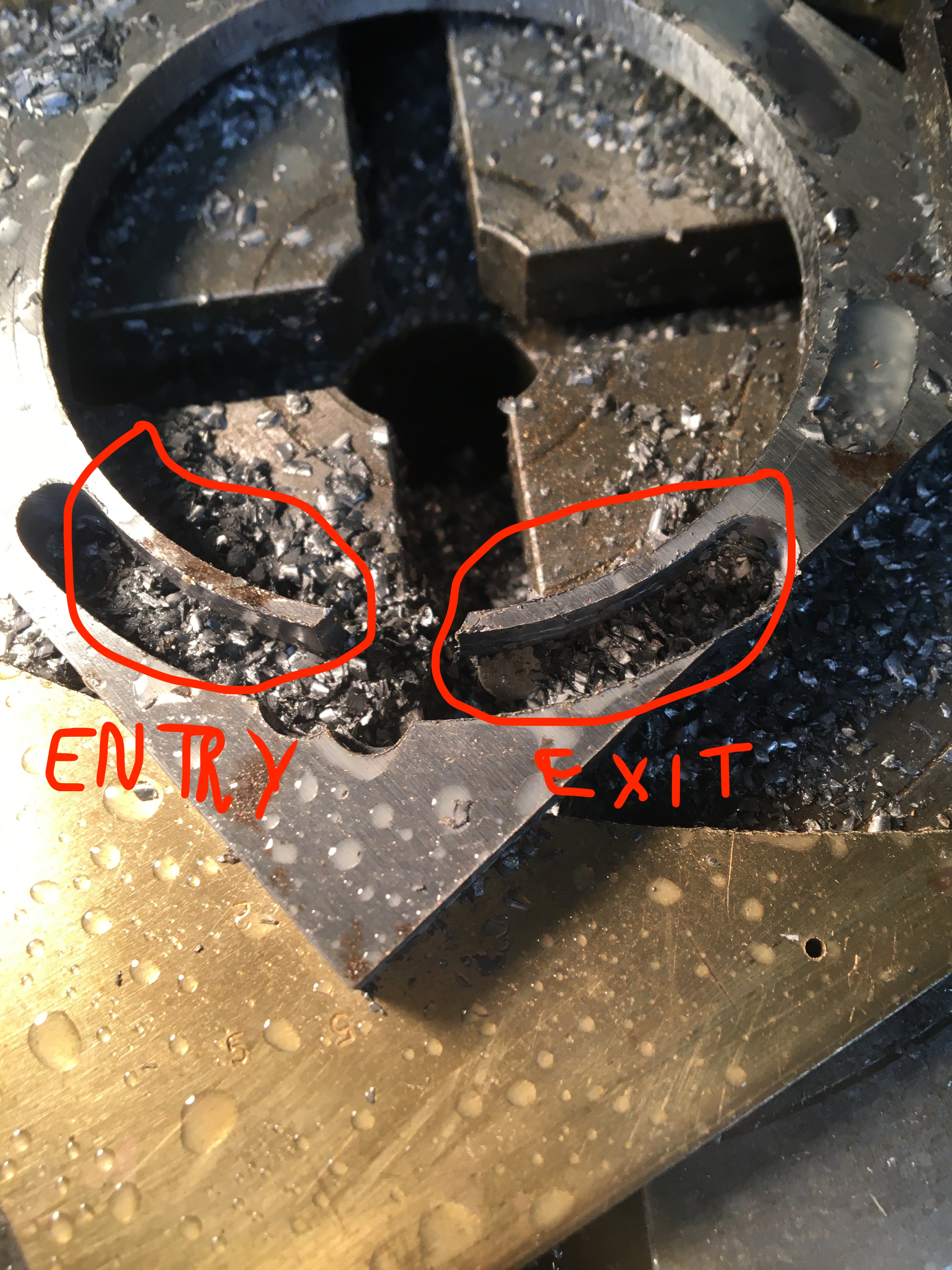
And here they are, still on the parent block of tool steel: if you can imagine the pointy escape wheel revolving clockwise in the middle, as the wheel brushes past the left hand pallet it gives it a push on the way up, and a corresponding tooth does the same to the exit pallet on the way down. Clear? If not, forget it for now, it’s too complicated. I’ll put a video up of it in the clock soon enough. The escape wheels need to lock onto the flat part of the pallet nibs by no more than 20 thousandth of an inch, and setting this up is key to the whole movement & performance of the clock.