Pendulum & mounting brackets
Having got the thing to “tick” I put it aside for 3-4 weeks while I dealt with a business, and made 2 new vices, both this time destined for the UK. They seem to have been very well received during the difficult “lock-down” against the pandemic, and I’m sure will provide hours of enjoyment to their new owners.
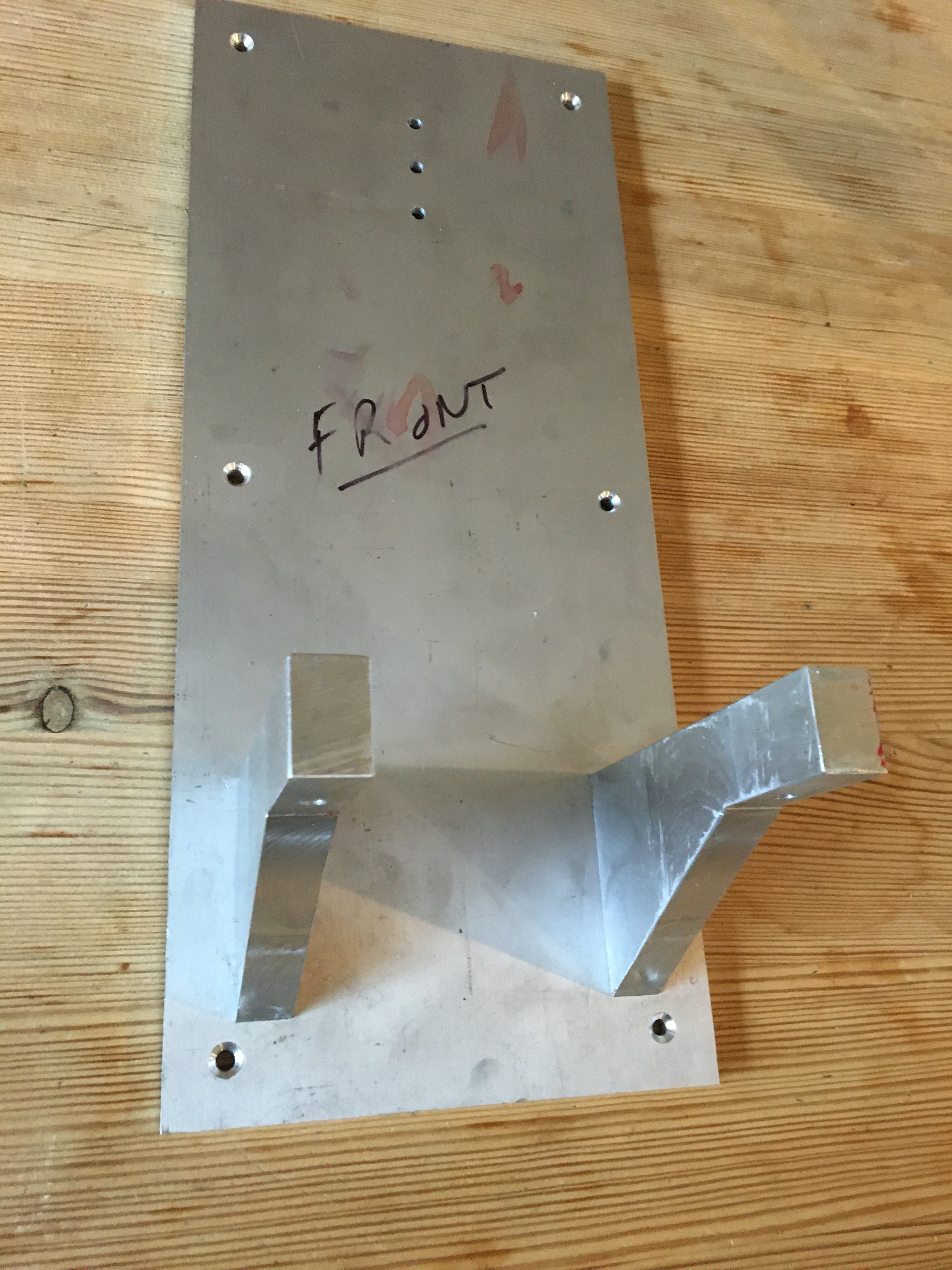
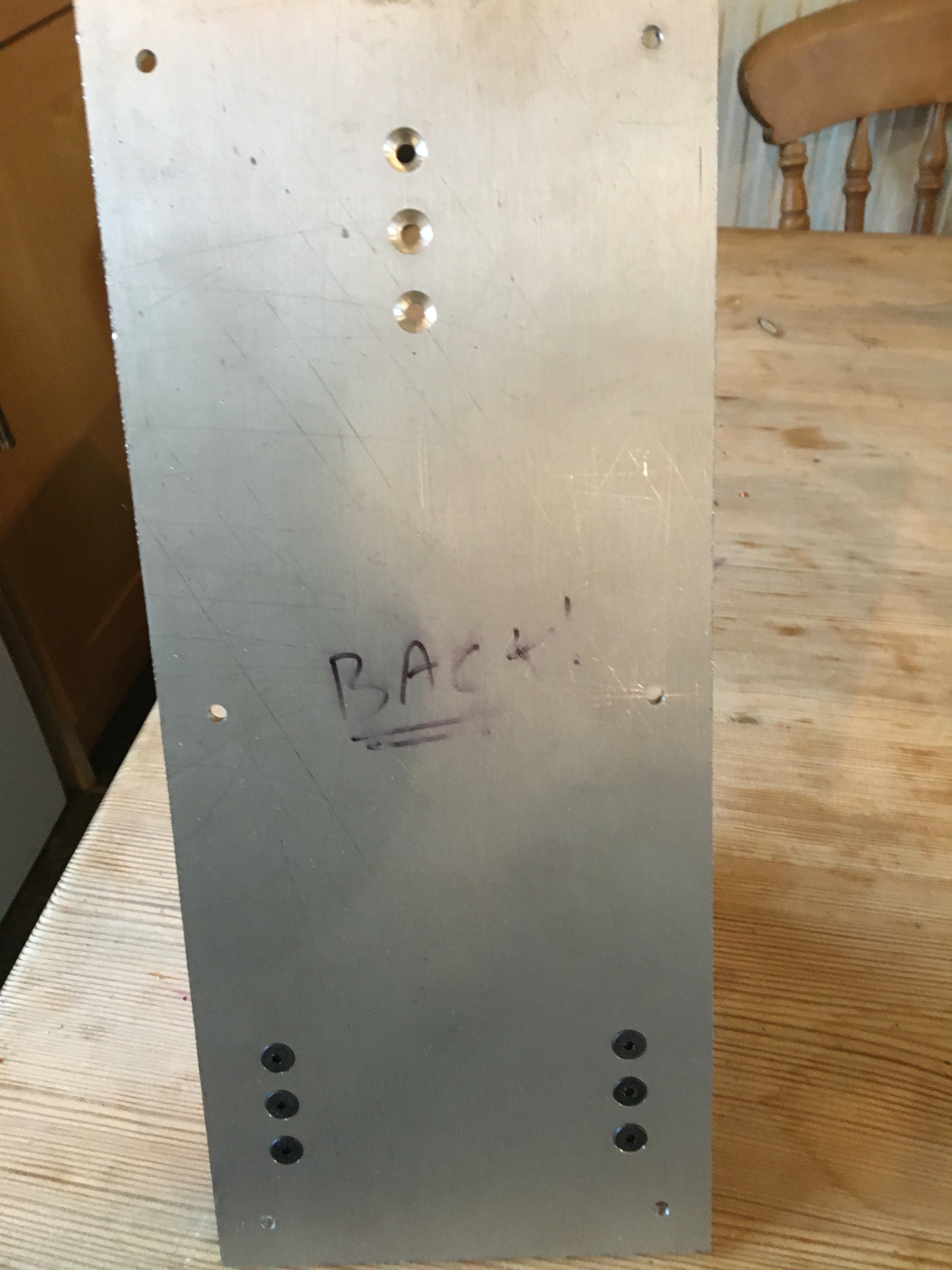
Having got those away, I used a facility on the Milling computer I’d never used before, called SDM (“Sub Datum Memory”), because there are 15 holes to be drilled in the backplate of the mounting, and the 2 arms need to be absolutely spot on, and the pendulum mount dead centre between the arms. After some messing about with the manual (a Chines translation, and a poor one at that), and a couple of you-tube videos, I worked out how to set it up, so I bolted the backplate to the milling table, and drilled away. there are 3 M5 screw holes for each arm, and it all went well. A test to the accuracy came when I drilled the arms the same way, and tapped them, and they went together on the backplate without even 1/2mm of allowance in the clearance holes for the screws. Amazing. I should have used it for the main plates in the first place!
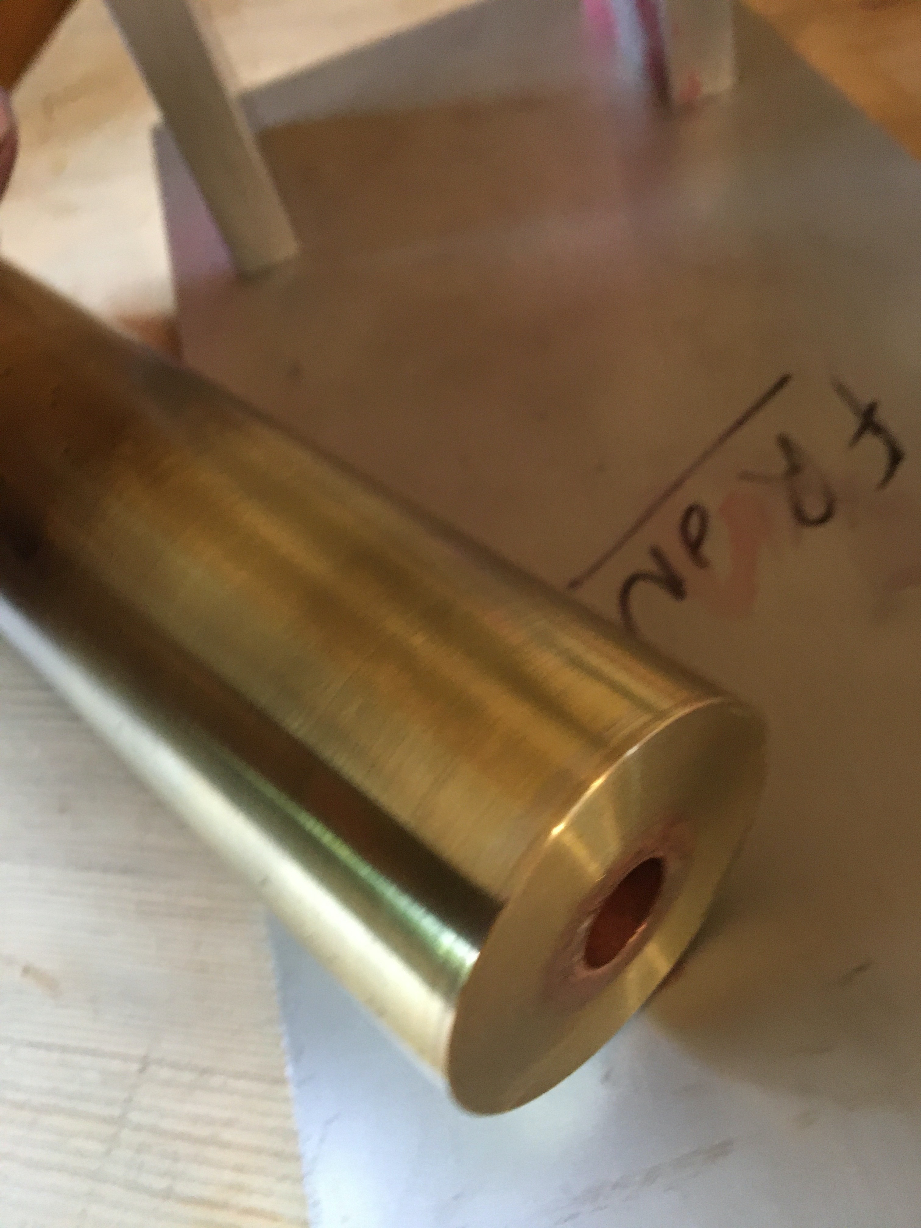
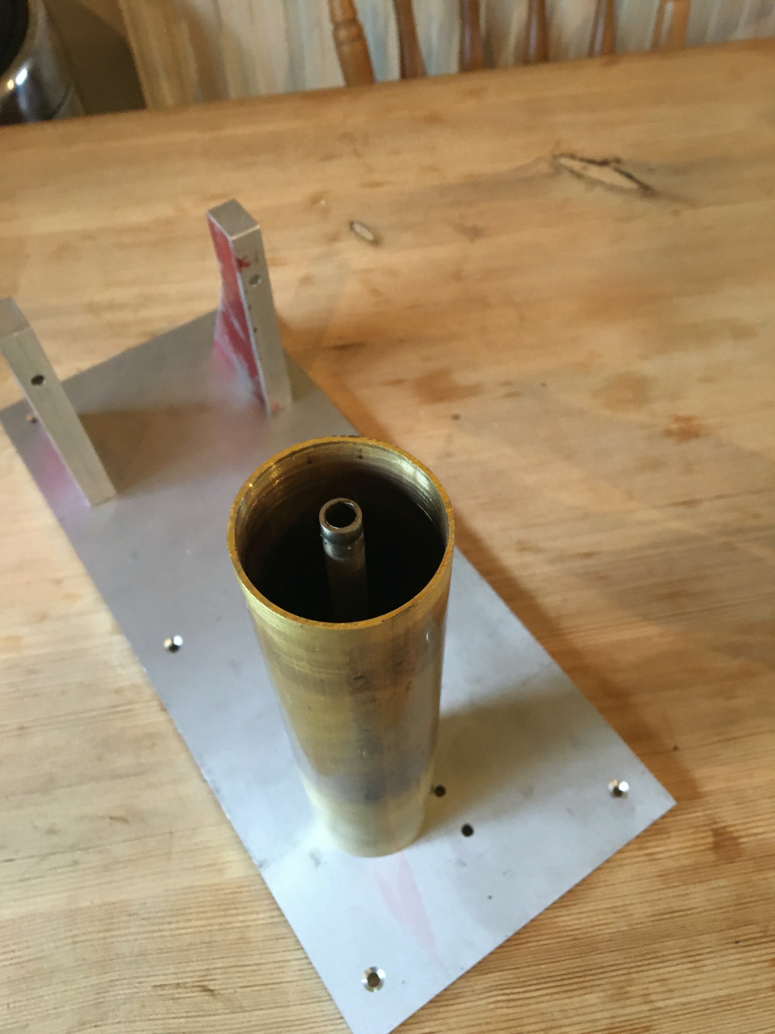
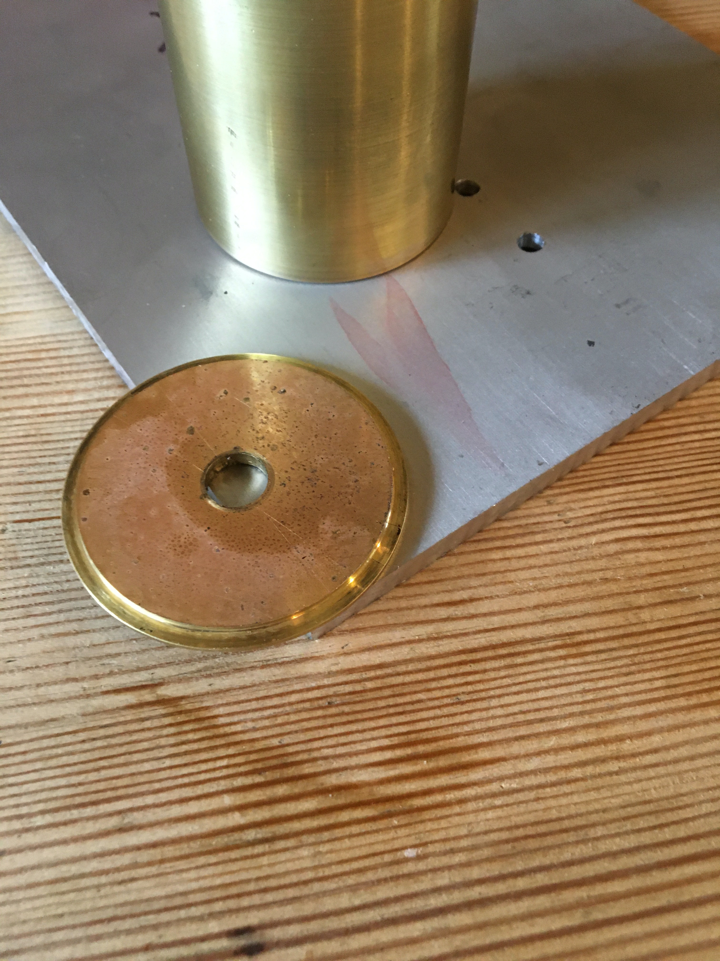
The next job was to make a start on a pendulum. I’d already decided to have a modern upgrade from the Invar rod that is on the existing clock, and to go for carbon fibre, which is about 1/10th the price, but absolutely beautiful to look at, with steel or brass rod for the crutch and beat adjustment screws. The choice for pendulum was either solid brass, or the lead filled brass casings that I’d bought with the metal for the clock. Having used steel on the last clock, it had to be brass, and casing was the easy option. A builder mate had let me have some lead offcuts from roof trimmings , so I silver soldered the bottom into the cylinder with a special tube made from Copper & stainless stee for the carbon rod, and drilled a filler hole before soldering on the top ready to fill.