Filling the casing proved to be easier than expected, the only issue being the time it took the lead to melt, but eventually it did, in two batches. It took ages to cool, but the final weight was 9 1/4lbs, which was right in the middle of the design weight of 9-9 ½ lbs.
The pendulum rod was next. I had a 1m length of carbon fibre, but needed to split it to give a brass section where the crutch touched, and to fit brass threaded sections at the top & bottom to join the suspension and pendulum bob adjusting screw & compensating tube. I cut the rod accurately, and drilled, glued & pinned the brass sections in without issue.
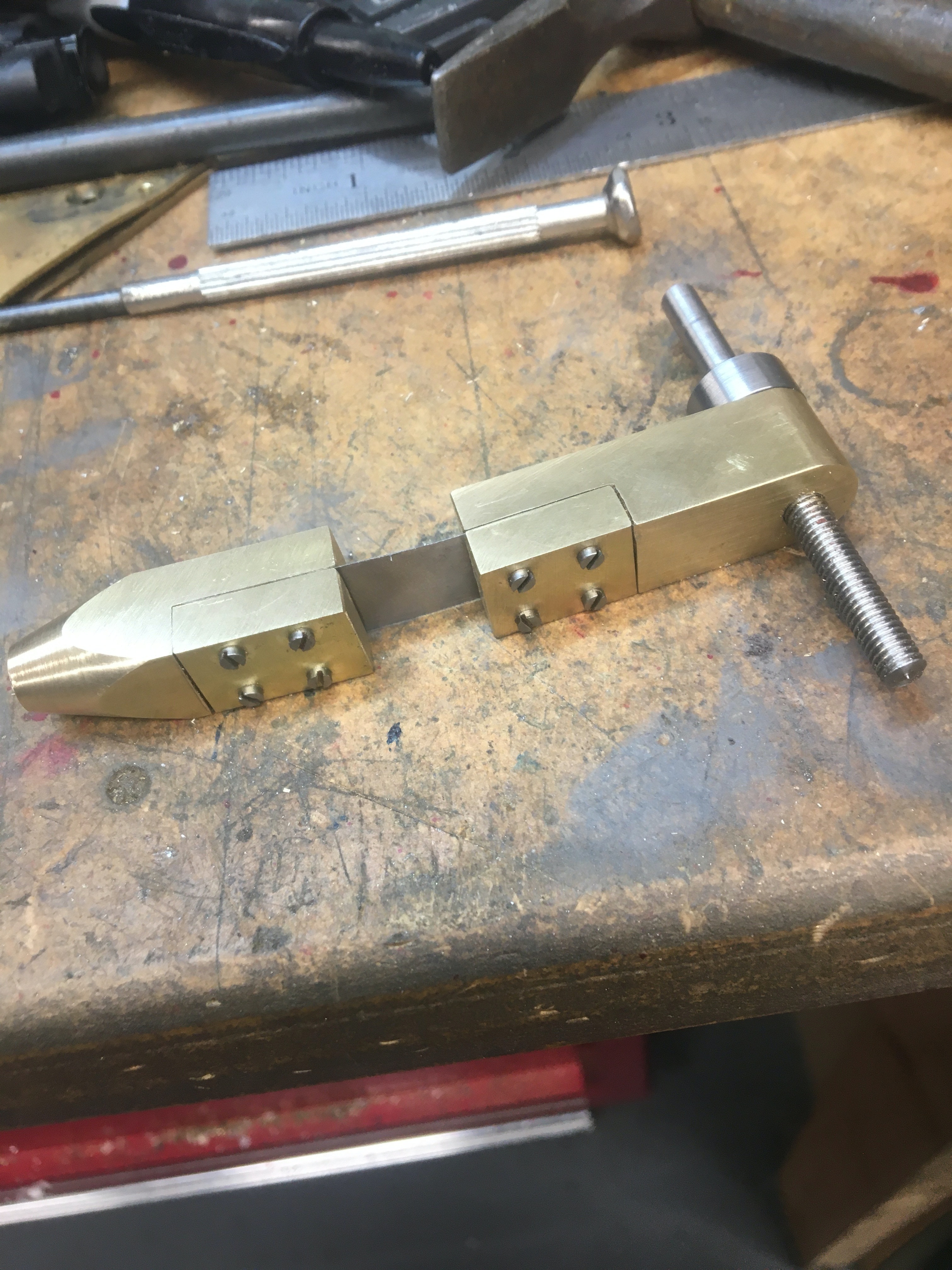
The suspension is pretty similar to the last clock, but more substantial because the pendulum is jolly heavy. Instead of sandwiched ⅛’ brass, this is ½”, sectioned to take a ¼” plate at each end, with a ½” steel spring between them. Again I used the SDM function to drill the 4 brass sections and a template to punch the brass, tapped the holes 10 BA and assembled it.
Pictures below:
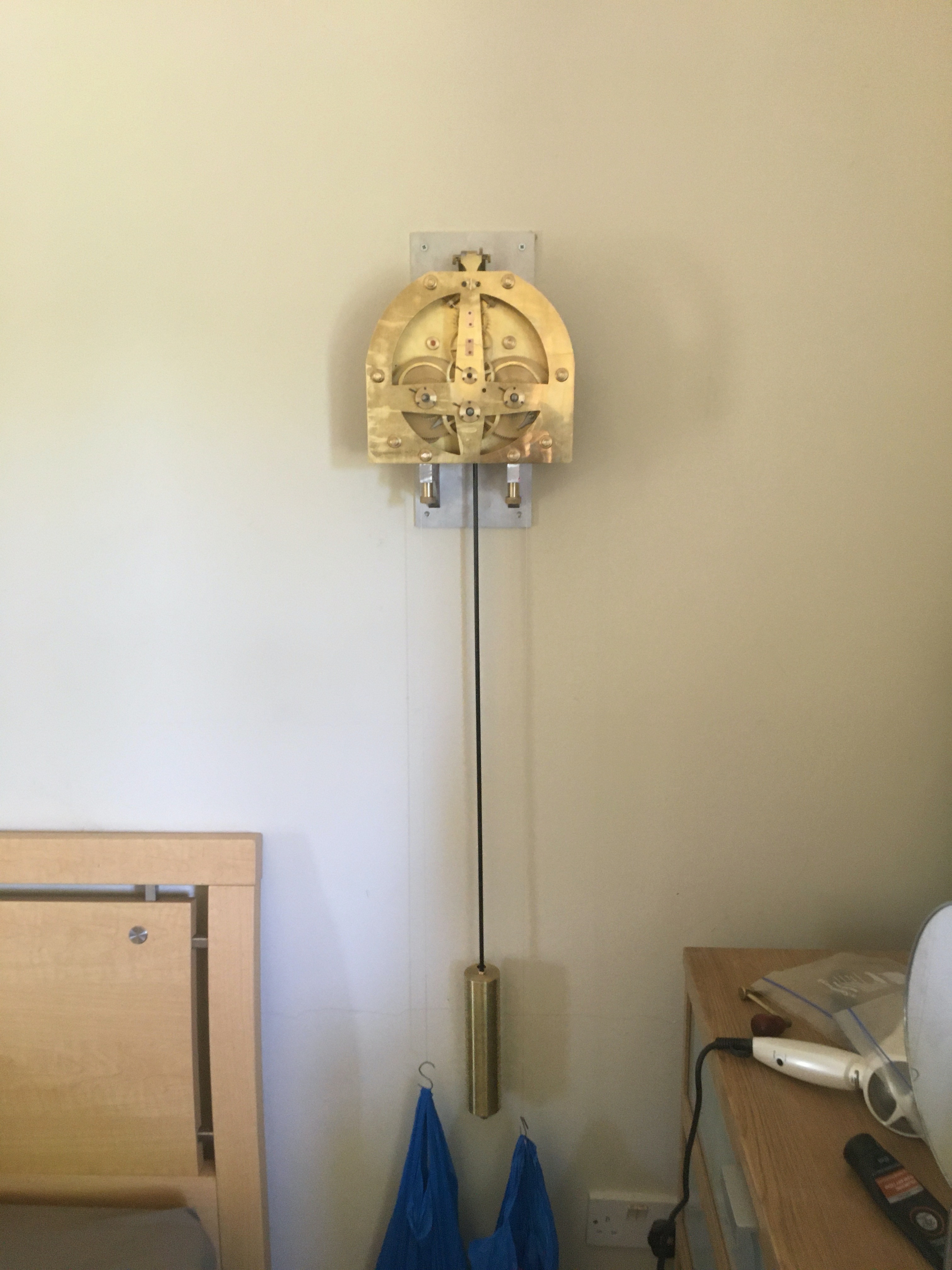
The moment of truth has finally come. The mechanism, mounting & pendulum assembly were ready for a first test, and the decision had to be made, where to test it? The test would be for about 3-4 months I guess as I have lots of work on, the chapter ring, motion work & hands need making, and the office & workshop are pretty dusty, filthy places. Eventually I settled on youngest son’s bedroom (I say youngest, but don’t get ideas - its 12 years or so since he slept in it, and he’s 6’2” and 17 stone in weight. He was an adorable little thing once but now a hulking monster).
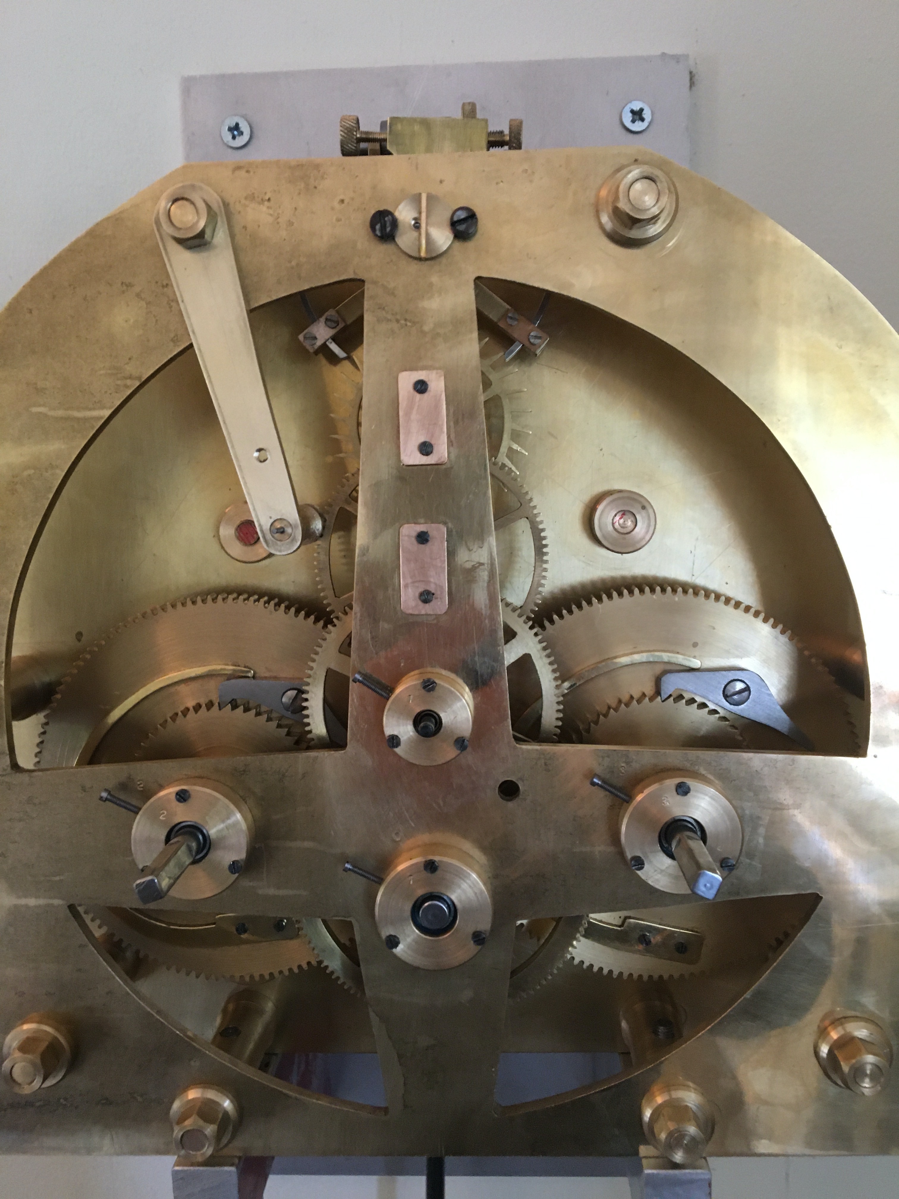
Anyway, the mounting was firmly fixed to the wall with 2” screws, plugged in hard, and the pendulum & works fixed to it without problem. The weights are 6 1/2lbs in each blue carrier bag on a dead drop, and 80lbs fishing line held them up. The clock started regularly, but stopped after 30 minutes or so - Problem No 1- the drive shaft of the left hand weight had come adrift from the pulley, so it was running on half power. The back was stripped, and it turned out the shaft hadn’t been loctited to the pulley in the first place. Easily fixed, second run started….
Problem No. 2. It stopped after 20-30 minutes with the escapement nowhere near where it was set up…. It turned out that the grubs-screws fixing the escapement to its arbour hadn’t been tightened. Easily fixed, again. Third run started…..
Well, I’m writing this 5 ½ hrs after that started, and I’m off to bed, and it’s still running. The last clock took 2-3 weeks to get to run consistently, but this sounds fine, is quieter then the last one - maybe because its directly into the wall, but possibly because of the power - weight - driving force ratios. Anyway, its far too soon to even think about timekeeping, just running is really great on its first day..
Video from You Tube is below, I’m a happy boy to see this run at last. Not the end of the project, but the beginning of the end I think…

The clock ran well for a week and I decide to crack on and make the seconds hand mechanism for it. This bolts to the left hand pillar around the 11 O’clock position, and picks up the drive from the third wheel via a 12 tooth lantern pinion to move the seconds hand. The movement is absolutely frictionless, but once fitted, it would only run for 3-4 hours before stopping. I did knock off a block on the beat adjuster and had to replace that, and found a stray tag of line catching the crutch, but having solved these, it doesn’t want to run well for more than 2-3 hours. Pictures & video of the seconds hand are below:
I eventually found that the depth of engagement of the seconds hand was the issue here, and after easing the pinion back a few thou, all was well.
I’m now going to leave the clock running while I make the motion work & hands for it.