GWR 14xx CLASS - Kit FIVE - Brakes, Reverser, Wheels
The numbers in brackets refer to the item numbers on the parts list.
Kit 5 duly arrived on time. On checking off the materials list a number of discrepancies were found. The Hex screws for items 50302, 50303 and the upgraded cross stretcher were all shorter in length than specified. A number of faulty components were subsequently found, one of the brake p.rod ends (50107) was drilled and tapped on the slew, tapped holes on the driving brake (50402) and leading brake (50403) supports did not match the supplied screws. These were longer than the depth of hole. Shorter screws were subsequently supplied.
For whatever reason replacement screws were slow in being supplied. This meant some disruption, waiting for correct screws to refit the slide bars and waiting for correct screws for the brake supports before refitting the cylinders.
There did seem to be some problems at Winsons, certainly much slower than previousy in replacing parts. Incidently I am still waiting for replacement connecting rod after 7 weeks. Anyway enough about the problems now on to the actual building.
Building was not carried out in the recommended sequence due to above problems. The fitting of keys to axles, crank pins to wheels and coupling rod bushes were straight forward. I then fitted the trailing wheels to their axle using loctite as instructed. Fortunately by good luck I got the distance between flanges correct, having carried out this operation before the belated instructions from Winsons. There was no guidance as to when to fit this assembly to the loco. I found the correct time was after the fitting of the brake shaft (50110), but before the rest of the brake gear. The wheels cover up the brake shaft brackets (50109). The main wheel and coupling rod assemblies were fitted without any problems.
The hand brake assembly (50405, 50406 and 50408) were installed but immediately removed until later to enable loco to be laid on its back more easily. It soon became apparent that the in order to fit the brake shaft brackets (50109) it would be necessary to remove the rear sub frames to get to the countersunk screws. A little more planning on Winsons part could have avoided this. Fitting of the brake shaft (50110), brake rocker (50409) and handbrake lever (50410) were straight forward except as previously mentioned the trailing wheels would interfere with this operation if they were in place.
The fitting of the driving and leading brake supports necessitated the removal of part of the motion to get a screwdriver to the inside of the frames. The same would have applied to the cylinders but these had been removed to fit the replacement slide bar support. Again if these parts had been supplied with kit 1 this could have been avoided. The brake hangers (50104) proved a little arkward to fit, very little space between hanger bracket and frames to get the nut in. The remainder of the brake gear presented no problems to fit. It was however noted that the handbrake handle was only restrained at the top of the handbrake column and not underneath, therefore allowing the handbrake to rise when releasing the brakes.
The fitting of the crosshead pump assembly presented a number of problems. First of all the pump fouled one of the angles on the motion plate supporting the slide bars. The only solution appeared to be to remove some material from the offending angle, but to do this it was necessary to remove the motion plate. Fortunately I could do this without disturbing the front part of the slide bars. Fitting the pump then proved arkward due to restricted access for a spanner. Finally when installed the motion became very tight. Subsequently it was found that the pump ram was nipped up tight. The only remedy was to slacken off the fixing bolts slightly, now I am concerned that they may work loose. Loctite may be the solution but very difficult to apply.
The fixing of the reverser gear was straight forward, however the bracket does appear to be very flimsy. At this point I decided to fit the second nut to the slide valve spindle to avoid any damage to the threads. However to be able to get the nut on I had to unbolt the slide valve spindle support, slide it towards the cylinder to get the nut on and then reassemble.
So far the installation of kit 5 has been the most frustrating due to the points raised above. Lets hope it was a one off.
The photos below show the completed frames at stage 5, minus connecting rod and reverser handles.
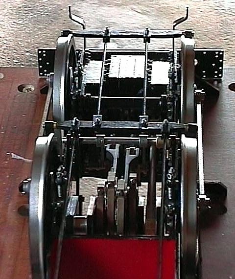
Brake rods and brake beams
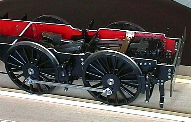
Main Wheels brake hangers and brake shoes
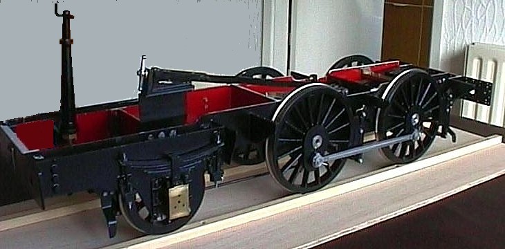
Frames at completion of Stage 5
Click here to go to next page (Smokebox-kit six)
Click here to go to previous page (Motion-kit four)