|
|
|
Triumph Mayflower
Service Bulletins
Triumphs forgotten car 1949 - 1953.
|
|
|
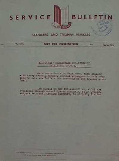
All service bulletins contained the text; "NOT FOR PUBLICATION, this Bulletin contains important service information and should be filed in your Service Dept. in the Bulletin Folder" (examples thereof above).
There are no doubt many service bulletins that are not shown on this site - will you share any such bulletins in your possession with myself and the Triumph Mayflower Club?
Service bulletins are listed by the Standard Triumph reference number, date of release / issue and description given. The wording and content have not been altered from the original. Any comments made by myself are in italic print.
![]()
V.41D. / 3.10.50 / Throttle control return spring
V.58.G / 4.6.51 / Body & Underframe Repair Manual - detail No 500737 V.60G. / 16.7.51 / Coil to distributor H.T. Cable V.66G. / 26.9.51 / Flywheel ring gear and starter motor V.68G. / 2.11.51 / Body & Underframe Repair Manual - detail No 500737 V.72G. / 2.11.51 / Modified carburettor jets V.71G. / 2.11.51 / Service instruction manual V.73G. / 2.11.51 / Engine manifold gasket V74.G. / 2.11.51 / Removal and installation of starter motor. V.76G. / 18.1.52 / Inlet & exhaust manifold packing V.77G. / 18.1.52. / Steering unit attachment - to trunion bracket V.82G / 4.6.52 / Underframe sub-assembly detail No. 300903 V.86G. / 12.11.52 / Loss of oil from rear axle cover plate - 2 Litre and Mayflower V.89G. / 23.1.53 / Care & maintenance of front suspension rubber bushes - Vanguard, Renown and Mayflower models. V.91G. / 4.2.53 / 31/2 Kilowatt heating & ventilating equipment - Standard Vanguard & Triumph "Renown" and Mayflower models V.92G. / 4.2.53 / Modification to top clutch operating rods detail Nos. 102334 (R.H.S. Mayflower), 106427 (Renown), 58797 (R.H.S. Vanguard) & 58922 (L.H.S. Vanguard) - R.H. and L.H. Steering Standard Two Litre cars, Triumph Renown and R.H. steering Mayflower models V.100G. / 10.7.53 / Lockheed stop light switch - Vanguard Series II & Mayflower V.105ED. / 6.10.53 / Schonitzer door locks - Triumph Mayflower models V.105G. / 6.10.53 / Schonitzer door locks - Triumph Mayflower & Renown models![]()
V.41D. / 3.10.50 / Throttle control return spring
With a small number of these cars the throttle adjustment return washer, which is specified for fitting between the return spring and the bracket on the cylinder head, was omitted.
With cars so affected there will be a tendency for the return spring to pass through the hole in the abutment and interfere with proper throttle operation.
Steps to deal with this omission in production have already been taken and all cars of this type released from the works after September 19th have been suitably equipped.
Where this difficulty is encountered a mild steel washer 1/16" thick, with outside and inside diameters of 7/16" and 1/8" respectively, should be fitted between the spring and the abutment bracket.
![]()
V.58.G / 4.6.51 / Body & Underframe Repair Manual - detail No 500737
Supplies of this
manual are now ready for distribution. Distributors and Dealers requiring this manual, should place their orders with the Spares Department. The price of this publication is 10/-, subject to the normal trade discount, and postage free.(Note:- 10/- equals £0.50)
![]()
V.60G. / 16.7.51 / Coil to distributor H.T. Cable
Instances have occurred, where this cable has been severed by vibration, when used in conjunction with the radio suppressor. The introduction of the sparking plug lead cleat, which was fitted to prevent Nos. 1, 2 and 3 cables making metallic contact with the engine, by restricting vibration, has prevented further fracture of this cable.
The cleat is shown fitted, in the illustration overleaf (to be included in the near future), its incorporation necessitating the lengthening of the three front sparking plug leads. The new length of leads are 11.7/8", 8.1/8" and 10.3/4", respectively, for Nos. 1, 2 and 3 cylinders.
When replacing this cable, following failure, the cable cleat, detail No. 60527, should be installed together with the necessary longer leads. The cable cleat may be obtained from our Spares Department.
The cable locating cleat and longer leads, were introduced in normal manufacture on engine No. TT.7487E and future, or on finished cars, at Commission TT.7413.
Return to contents![]()
V.66G. / 26.9.51 / Flywheel ring gear and starter motor
It is particularly important, when fitting a new replacement flywheel and/or starter motor, to quote the engine number of the unit for which theses are required.
After 1,000 engine units, a different pitch starter motor pinion and flywheel ring gear were introduced.
Prior to the change in the ring gear and starter motor pitch, the flywheel holding bolts pitch circle was increased in diameter and this was naturally accompanied by a similar modification to the drilling and tapping of the crankshaft for the holding setscrews.
The following are the items affected by these changes with introduction points:-
|
Detail Number |
Item |
Incorporation point (Engine Nos) |
|
300123 |
Flywheel (8/10 D.P.ring gear 92 teeth) |
TT.1E - TT.144E |
|
300070 |
Crankshaft |
TT.1E - TT.144E |
|
300415 |
Flywheel (8/10 D.P. gear modified holding bolt holes 92 teeth) |
TT.145E and future |
|
300414 |
Crankshaft (drilled and tapped to suit 300415) |
TT.145E and future |
|
200325 |
Starter motor Lucas type V.154 (8/10D.P. pinion 10 teeth) |
TT.1E - TT.1000E |
|
300168 |
Flywheel (10/12 D.P. Gear 117 teeth) |
TT.1001E and future |
|
200535 |
Starter motor Lucas type L.3 (10/12 D.P. pinion 9 teeth) |
TT.101E and future |
![]()
V.68G. / 2.11.51 / Body & Underframe Repair Manual - detail No 500737
It is apparent from the enquiries that our Technical Services Department are receiving with regard to chassis dimensions and other data for accident repair work, that many of our agents have not, so far, ordered this
manual, in spite of the issue of our Bulletin V.58G.The price of this publication, as previously stated is 10/-, subject to normal trading discount and post free.
(10/- equals £0.50)
![]()
V.72G. / 2.11.51 / Modified carburettor jets
In order to reduce the idling speed of the engine, when the starter side of the carburettor is in use, it has been found necessary to modify the jet setting.
The existing two 4.5 Air Jets, have been discarded, thus leaving the tapped orifices, which provide an effective diameter air intake of 8m/m. This increase in the potential air intake necessitates a slight adjustment in the size of the Petrol Jet - a 135 Jet replacing the one of 120 previously used.
The carburettor jet setting for this model now becomes:-
|
Choke |
21 |
Air bleed for pilot |
2.0 |
|
Main jet |
105 |
Needle valve |
2.0 |
|
Correction jet |
220 |
Starter air jet (fixed) |
8.00 (2 off) |
|
Pilot jet |
45 |
Starter petrol jet |
135 |
This modification was introduced in production at engine TT.11412E
![]()
V.71G. / 2.11.51 / Service instruction manual
This
manual will shortly become available for distribution and should be ordered through normal channels from our Spares Department, under detail 500833.This manual has been provided in loose leaf form, thus facilitating revision, as such becomes necessary.
The manual is priced at £1.10.0d., postage free, and subject to normal trading discount. As it is found necessary to revise sections, or portions of sections, the amended sheets will be supplied without further charge.
To enable the supply of amendments, as theses are issued, you are requested upon receipt of this manual, to complete and return the requisition form which is attached to the inside of its cover. The completion of this requisition form will ensure routine despatch of such amendments, as they become available.
(Note:- £1.10.0d. equals £1.50)
![]()
V.73G. / 2.11.51 / Engine manifold gasket
In view of a number of failures with Mayflower gasket, detail 43859, it has been found necessary to modify this packing.
A new gasket, detail 103978, has been introduced, which is made from a single thickness of asbestos with a steel plate interposition, as was previously used.
The new gasket should be used foe all replacements and such supplies of the former gasket, as are held, should be used up for replacements on the 8HP. Models, for which purposes they are completely satisfactory.
When fitting the new type of gasket, the steel surface should be placed towards the manifold.
Return to contents![]()
V74.G. / 2.11.51 / Removal and installation of starter motor.
Owing to the small amount of clearance between the starter and various of the chassis components, difficulty may sometimes be experienced in manoeuvring this component out of, or into, its housing, when the necessity for an exchange of units arises.
When difficulty in removing, or fitting the starter motor is experienced, owing to its proximity to the chassis frame and engine, sufficient additional manoeuvring space may be obtained, by moving the engine sideways slightly on its flexible mountings.
Movement of the engine on its mountings should obviously limited to the minimum required to enable the withdrawal or installation of the starter motor.
Return to contents![]()
V.76G. / 18.1.52 / Inlet & exhaust manifold packing
Instances have been reported, where the manifold packing has disintegrated, owing to distortion of the two clamp brackets, detail 100646. This difficulty has also occurred, in a very few instances, with the modified washer, mentioned in Service Bulletin V.73G.
As a result of the distortion of these clamp brackets, it has been found necessary to introduce a stouter clamp bracket, detail 33148. The new clamp may be recognised by the depth of its centre boss, this being approximately 11/16" compared with approximately 9/16", with the earlier bracket.
Instances of manifold washer failure have been reported with Mayflower models, where this difficulty has been explained by the bolts "bottoming" in their threaded holes in the cylinder block, before the packing is firmly gripped. To meet such difficulties, a plain washer should be fitted on each of the two bolts, between the manifold and spring washer.
To meet cases of manifold clamp distortion, the later bracket, detail 33148, should be fitted with the longer studs, detail 103195.
The modified clamp bracket and longer studs were introduced in normal production at Eng. No. TT.13283E.
Return to contents![]()
V.77G. / 18.1.52. / Steering unit attachment - to trunion bracket
In a number of cases, slackness has developed between the trunion bracket and the steering unit, owing to the studs working loose on this bracket.
As a result of these complaints it has been decided to replace the plain washers, detail No. WP.0009, which was fitted under the self locking nuts, by tabwashers, detail No. 104329. The tabwashers should be fitted, as shown in the attached illustration (to be included in the future).
Whilst this difficulty is not considered sufficiently widespread to justify special recall to Agents' premises, it must not be unduly delayed and the modification should be carried out at the first opportunity, when the cars concerned are returned for routine servicing.
These tabwashers were introduced, on the assembly line, at commission No. TT.14814.
(NOTE from S. Coulman:- V.77G. advises that the retaining bolts - principally the top -for the steering box fall out due to vibration - I've had this happen - which could result in collapse of the steering box if a 'pot hole,' or similar, is met in the road. If you buy a restored Mayflower, or undertake this work yourself, make sure that you fit tabwashers - it could prevent an unfortunate incident!!)
Return to contents![]()
V.82G / 4.6.52 / Underframe sub-assembly detail No. 300903
As a convenience to Repairers, when dealing with heavy frontal damage, special arrangements have been made to make available a sub-assembly as per drawing overleaf (to be included in the future).
The supply of the sub-frame assemblies, which are available through normal spares channels, at £17.10.0d subject to normal trading discount, is strictly limited.
(Note:- £17.10.0d equals £17.50)
Return to contents![]()
V.86G. / 12.11.52 / Loss of oil from rear axle cover plate -
2 Litre and MayflowerVanguard and Renown
In view of the number of complaints which we are receiving of oil leakage from the rear axle cover plate due to loose holding bolts, it is most important that the tightness of these bolts should be scheduled for attention during pre-delivery checks and also when carrying out early maintenance inspections.
A certain amount of initial packaging shrinkage can occur at this point and thus prevent the tab-washered bolts providing the necessary clamping pressure required to ensure an oil tight joint.
When checking these bolts for tension they should be tightened up to a torque figure of 16 - 18 Ibs. ft. - it will be necessary to release the tabwashers and after carrying out the check to tap these up so as to secure the nuts in their tightened positions. Where tabwashers are damaged when carrying out this check, they must naturally be replaced.
Mayflower
Although complaints have not been reported with regard to leaking oil from the axle cover plate, a certain amount of initial packing shrinkage may occur and the same precautions should be taken during pre-delivery and early maintenance checks as for the other models. With this model, owing to different conditions, tabwashers are not used. The nut tightening torque for this model should be the same as that specified for the Two Litre models.
Return to contents![]()
V.89G. / 23.1.53 / Care & maintenance of front suspension rubber bushes -
Vanguard, Renown and Mayflower models.There is some evidence that the importance of protecting these rubber bushings from oil or grease is not generally appreciated. These bushes, being made of natural rubber, their useful life will be considerably reduced by oil or grease contamination.
It is not only important that these rubber bushes are not subjected to oil spraying when chassis lubrication is being carried out, but also that they should be assembled dry when fitting replacements after first cleaning all associated details of grease and oil. French chalk, however, is a legitimate aid to assembly, but the use of soft soap, petrol or other such liquids is inadmissible,
When fitting these rubber bushes to a Mayflower, the bushes should be first centralized by sight in relation to the fulcrum bosses, and the wishbone arms worked to and fro as the nut and washer are tightened hard against the shoulder on the fulcrum bracket. The working of the wishbone arm assists in the maintenance of an even flange.
Although with the Vanguard and Renown models it is not entirely necessary to centralize the rubber bushes in relation to the wishbone bosses, as they centralize automatically in service, to do so will prove advantageous to assembly. The procedure to that indicated for the Mayflower should be used when tightening the nut and washer against the shoulder on the fulcrum bracket.
Return to contents![]()
V.91G. / 4.2.53 / 31/2 Kilowatt heating & ventilating equipment -
Standard Vanguard & Triumph "Renown" and Mayflower modelsThere have been a number of complaints with this equipment which, upon investigation, have been found to be explained by incorrect adjustment of the controls.
Instructions, issued by the manufacturers of the equipment, are attached for the guidance of repairers, when investigating difficulties in connection with the equipment's operation.
(Note:- attachment temporarily lost)
Return to contents![]()
V.92G. / 4.2.53 / Modification to top clutch operating rods detail Nos. 102334 (R.H.S. Mayflower
), 106427 (Renown), 58797 (R.H.S. Vanguard) & 58922 (L.H.S. Vanguard) - R.H. and L.H. Steering Standard Two Litre cars, Triumph Renown and R.H. steering Mayflower modelsSince manufacture of these models commenced a modification has been introduced in connection with the Top Clutch Operating Rod. This alteration was made with a view to eliminating the sharp bends at each end of the rod, which were previously used. These rods have proved susceptible to fatigue fracture, where large mileages, or exacting conditions of clutch operation, are involved.
Repairers are recommended to make this modification when fitting a new clutch assembly, as the installation of such a unit is likely to precipitate a failure of a fatigue nature.
Return to contents![]()
V.100G. / 10.7.53 / Lockheed stop light switch -
Vanguard Series II & MayflowerLockheed stop lamp switch, S.M.C. Part No. 501004 (Lockheed Part No. 29813) has now been rated by Messrs. Lockheed for replacement only in installations up to 24 Watts loading and must NOT be used as replacements on any Vanguard or Mayflower vehicle. All replacements MUST be of the Lucas stop lamp switch, S.M.C. Part No. 62057 (Lucas Part No. 31082). This can be identified by the vertical terminals, raised plastic insulator, and hexagon size of 1" across flats.
Your stocks of switch S.M.C. Part No. 501004 (Lockheed Part No. 29813) may be used on the "Renown" or any similar Lockheed installation, where the total brake lamp loading does not exceed 24 watts.
Return to contents![]()
V.105ED. / 6.10.53 / Schonitzer door locks - Triumph Mayflower models
Messrs. Wilmot Breeden have prepared the
enclosed instruction book, dealing with the adjustment and fitting of the door locks of their manufacture, which are used on these models.The mailing of these booklets has necessarily had to be limited to our home and overseas distributors, but additional copies for your dealers may be obtained, owing to the co-operation of these suppliers, direct from the firm concerned, i.e. Messrs. Wilmot Breeden Ltd., Equipment Department, Goodman Street, Birmingham. 1. At 1/6d. each (Nett).
Copies of similar instructions for the Triumph "Renown" models may also be obtained through the same channels at the price quoted.
(Note:- 1/6d. equals £0.07.5)
![]()
V.105G. / 6.10.53 / Schonitzer door locks - Triumph Mayflower
& Renown modelsMessrs. Wilmot Breeden have prepared most instructive
booklets covering the fitting, removal and adjustment of the door locks of this type, which are fitted to our Triumph Mayflower and Renown models.Messrs. Wilmot Breeden have been kind enough to agree to supply copies of these manuals, insofar as supplies permit, at 1/6d. each (Nett). Dealers who wish to obtain copies of these manuals should apply direct to Messrs. Wilmot Breeden Ltd., Equipment Department, Goodman Street, Birmingham. 1.
Back to top Return to Homepage![]()
|
This site has travelled |
|
miles since January 2001. |
©2001 - 2012 TRIUMPH MAYFLOWER HISTORIAN
. All rights reserved. You may not copy or distribute photographs or information from this site without prior written permission. Information is believed to be accurate, however due to the many and dynamic sources I do not warrant the validity of facts, dates, availability or other information shown here. Please confirm dates and venues of any event mentioned before you travel.Revised: October 2012