 Go
to the Archive index
Go
to the Archive index
The story begins in Italy, for our purposes, in 1946. Vincenti Piatti had designed a 50cc engine unit for driving portable lathes and also foresaw the possibilities of this engine power-assisting a bicycle - the Mini Motore. Italy was suffering the results of six years of war and there was a huge demand for cheap personal transport, fuel being scarce and expensive.
In 1948, George Murray Denton was holidaying in Switzerland and, as he recalled in an article in Classic Bike in 1985, "...I followed a cyclist who not only free-wheeled downhill but shot uphill with no loss of speed and with only occasional pedalling. There was a device behind the saddle which emitted blue smoke and a noise like a bored-out wasp. It was an Italian Mini Motore." On his return to England, George found that Trojan of Croydon - remember their two-stroke Brooke Bond Tea vans? - were making them under licence for sale in the UK. George later became Sales Manager of Trojan and reckoned that, by the time sales were overtaken by the more technically advanced Cyclemaster in 1951, over 100,000 must have been sold.

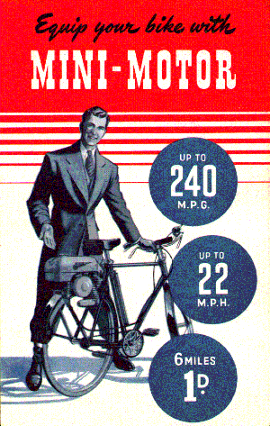
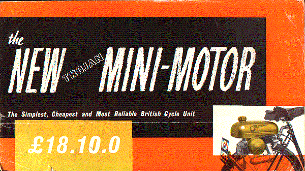
The Mini-Motor opened up a whole new market in post-war European cycle attachments. So much so that, in a four page review of cyclemotor attachments in the December 14th 1950 issue of The Motor Cycle, no fewer than ten were on the market with an eleventh due to go on sale the next spring. The Mini-Motor's weight was quoted as 22lbs, tank capacity 3 pints, price £21. Roy Morton was present at the "Box Hill Trials" in February 1951 and he summed up his views thus: "These little units take all the work out of cycling, leaving only the pleasure". The Mini-Motor was as revolutionary in its day as the NSU Quickly would become a few years later.
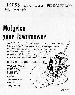
Trojan produced the Mini-Motor in several guises. As well as the cyclemotor unit, it was sold as a small industrial engine too; there was also a "Mini-Mower" - a bolt-on attachment that converted lawn mowers to power operation - and an outboard motor for small boats. The industrial version of the Mini-Motor was usually mounted on a steel stand with a rectangular petrol tank above the engine. Several of these engines had fan-cooling with blades on the flywheel directing air through an aluminium alloy casing that covered the magneto side of the engine.
A 75cc version of the engine was also produced. This was advertised as being suitable for powering carrier tricycles.
Trojan made a half-size non-working model of the engine too. This was used by their salesmen to demonstrate the engine to prospective agents.
The Trojan was not the only Mini-Motor. Production of the Italian-built machine continued and another version of the engine was made in France. British and Italian machines looked identical but the French model used a different design of tank, considerably altering its appearence.
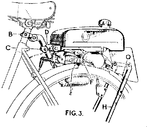
Although the Mini-Motor cycle unit was changed several times throughout its production; its basic design remained the same. The backbone of the device was the fuel tank. The tank had a hinge at the front; clamped to this was a rod which, in turn, clamped to the cycle's seat pillar. A "U" shaped steel hoop fitted over the cycle's rear wheel. The two prongs of the "U" were secured to the ends of the wheel spindle. The rear of the fuel tank was attached to this hoop by a mechanism which would raise and lower the tank. The engine itself was fitted below the tank with the cylinder facing forwards. A friction roller was mounted directly on to the crankshaft. When the tank was lowered, this roller would press onto the top of the tyre tread and would drive the cycle forward. Apart from some pre-production units which were permanently held in contact with the tyre by spring pressure, all subsequent Mini-Motors had some form of lifting/lowering mechanism. This was usually controlled by a trigger or ratchet lever on the handlebar. A more unusual version was controlled by a lever to the rear of the machine (If this was supplied, the handlebar lever and cable were not fitted). When the rear lever was fitted the rider had to dismount and raise or lower his cyclemotor while stationary. Strangely, Mini-Motor instruction books printed from December 1949 onwards contain no reference to this rear lever mechanism although there are is photographic evidence that some machines did use it.
Yet another mechanism was fitted to the 75cc carrier tricycle version. In this case the engine was hingeded at the rear and a long lever raised and lowere the front of the engine.
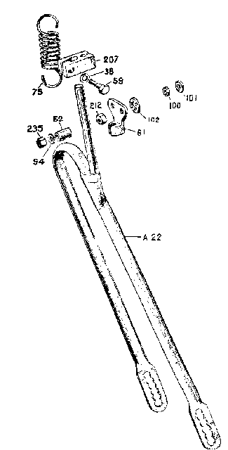
Several of the design changes made to the Mini-Motor concerned the hoop and the raising & lowering mechanism. The earliest machines had a hoop in one piece. This was slotted at its lower end where it fitted over the cycle axle, thus allowing for adjustment to different sizes of cycle wheel. A rod at the upper end passed between two guide rollers. The engine crankcase was bolted to the tank with extra-long studs and the rollers were mounted on these studs. A tension spring pulled the tank down, pressing the drive roller onto the tyre. The drive could be disenganged by lifting the tank using a handlebar lever and Bowden cable control. Very few of these early pattern Mini-Motors have survived in their original condition. As Trojan made each improvement to the design, a conversion kit would also be produced so that owners of older machines could also benefit from the improvements.
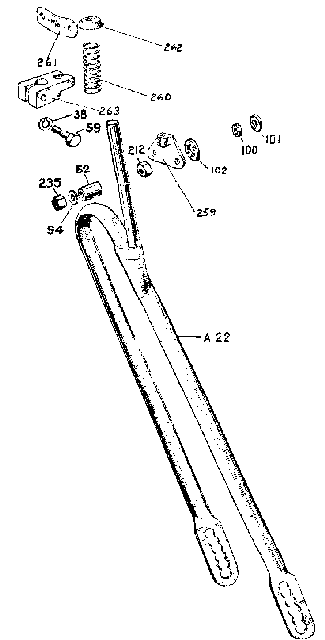
The use of a tension spring to hold the roller onto the tyre was found to be unsatisfactory. The engine unit was liable to bounce up and down by a small amount on uneven road surfaces. This caused variations in the roller contact pressure and the drive would slip leading to not only loss of driving power, but also damage to the tyre. An early improvement was to reverse the mechanism so that the cable control pulled the engine down onto the tyre. A compression spring would lift the engine when the drive was disengaged.
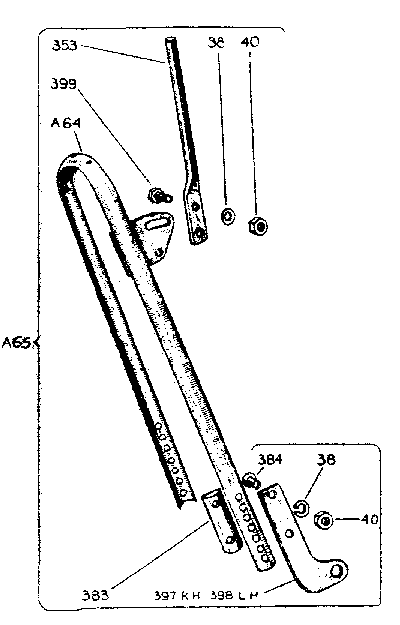
The next improvement in this area was to the hoop. The new design was bolted together instead of being in one piece; the length of the hoop could be varied with the adjustable end plates. Because the new hoop was adjusted at the endplates instead of at the rear wheel spindle; the rear wheel of the cycle could be removed, to change a tyre for instance, without having to readjust everything when it was replaced. The next inprovement was to mount the guide rod on a sector plate so that its angle could be changed. This made fitting the Mini-Motor easier because it provided a greater degree of adjustment. The original hoop could be awkward to fit on some cycles, especially if one of the tall pre-war style of roadster bicycles was being used.
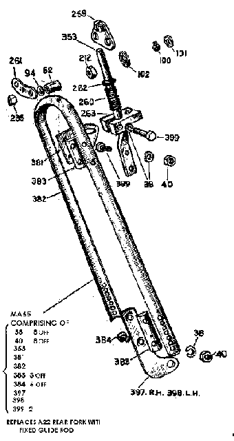
Finally, although the new raising and lowering mechanism was a great improvement on the old one, it still had one minor problem. If the cycle was being used with the engine disengaged the roller could sometime be bounced into contact with the tyre, particularly if luggage was being carried on the top of the tank. A new toggle-action mechanism was provided that provided greater support to the tank in the raised position. Since it no longer used guide rollers on the crankcase studs, this mechanism also paved the way to impovements in engine mounting.
The early models (Mark I & Mark II) had the engine mounted at two points: a single bolt at the top that fitted into a boss cast into the cylinder block and the two studs at the rear of the crankcase. From the Mark III onwards the engine was held beween sideplates that fitted over the crankcase studs.
There were at least four different designs of handlebar lever used to controlled the engine engagement mechanism. The various possible combinations of handlebar lever and drive control mechanism meant that a huge variety of different control cables were made. The fact that conversion kits for the drive control were available exacerbated this problem since a machine with an early lever could have been changed to a later drive control. In addition, cables were also available in extra long versions for tandems.
The friction drive roller was also subjected to change. The first models, like most other makes of friction drive cyclemotor, had a roller with deep, straight-cut teeth. A carborundum surfaced roller was then introduced. This gave much better grip on the tyre, especially in the wet. However, it also increased the rate of tyre wear. Finally a steel roller with shallow curved teeth in a herringbone pattern was adopted.
The flywheel magneto fitted to the Trojan Mini-Motor was either a Miller or a Wico-Pacy Bantamag. Engines equipped with the Miller magneto were identified by stamping a letter "Z" as a suffix to the engine number.
The Mark I Mini-Motors were not originally equipped with decompressors and this could cause problems with starting, especially in the wet. The roller did not always have enough grip on the tyre to overcome the engine compression. A special technique was needed to get the engine going. This was to first engage the roller on the tyre and gently wheel the cycle backwards until the engine compression started to resist. Next, disengage the roller, mount the cycle and pedal off. Then engage the roller. The crankshaft then had to make almost a complete revolution before it hit compression, by which time the combined forces of flywheel inertia and the drive from the tyre were enough to force it over top dead centre. The introduction of a decompressor on later models made it possible to use a more conventional starting procedure. Evidently, the decompressor was optional for a while and some Mini-Motors were produced with the cylinder head machined to take one, but with a blanking plug fitted instead. Again, conversion kits were produced for improving the earlier models
Although some Trojan publicity referred to a new stronger crankshaft on the Mark II, the only change made was to drill and peg the crank pin to the crank webs. This change was made to prevent over-enthusiastic mechanics from twisting the crank when changing the roller.
Fuel tanks all had the same basic shape although the change of engine mounting on the Mark III meant changes to the tank brackets. Early tanks were brazed, later ones were welded. Some tanks were provided with loops underneath so that luggage could be carried on the tank, held by straps or "aerolastics". The tanks, up to and including the Mark III, were nearly always painted blue. At least one machine was finished in white in 1951 and used as a demonstrator and show exhibit. It is also possible that some were finished in black. When the Mark V was introduced, it had a new design of tank: it looked basically the same shape but a little more rounded. The major difference in the Mark V fuel tank was that it was no longer load-bearing. The engine was mounted on a pressed steel sub-frame and the tank was held onto this frame by three studs. The mountings for the rear number plate were moved off the back of the tank to brackets on the hoop and the standard colour changed from blue to polychromatic gold.
The Mini-Motor assembly line was on the north side of the main Trojan factory, running west to east. The production area was about 50 foot square whilst the assembly and test area was about 12 feet wide and about 100 feet long. Items like magnetos, sparking plugs, carburettors, ball races and piston rings were bought in but the rest of the parts were made on site.
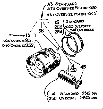
Pistons were first machined on the inside of the skirt and the bottom edge was faced. Next, locating on to the machines by the inside skirt, the gudgeon pin hole was drilled, then reamed. Thirdly, the piston was mounted on a fixture in a lathe and was held by a draw bar through the gudgeon pin hole; thus enabling the outside, the ring grooves and the crown to be turned to size, using paraffin as the coolant. Pin holes were drilled and pins fitted to stop the two rings turning in their grooves.
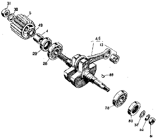
The crankshaft assembly was made up of four main parts: the magneto side crankshaft, the driving side crankshaft, the crank pin and the con rod. The two crankshaft halves were pressed onto the crank pin with the roller bearings and con rod in position. The next operation was to grind the places where the main ball races went on the assembly to the correct diameter and the correct distance between the faces, thus maintaining a fairly tight tolerance. The crankcase halves were machined in the normal way; so too the cylinders, which were bored and honed. All cylinders were bored and honed at the Trojan factory and there was a small section that did nothing else.
Moving on to the assembly line itself, studs were inserted using a hand stud insertion tool and the engines were assembled in much the same way.
There was a test rig against the north wall of the building that contained positions for twelve engines. An engine was put in the fixture and turned by electric motor. After a 20 minute running-in period, the sparking plug was fitted, petrol/oil mixture was turned on to the carburettor and the electric motor was used to start the engine. The exhaust was connected to an extraction pipe. After a successful running-in period the engine was removed from the test bed, cleaned and the fuel tank bolted on or, if it was an industrial unit, the frame of whatever the customer had ordered was fitted. The completed unit was then passed to Stores ready for dispatch.
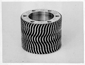
Works photo of the herringbone roller
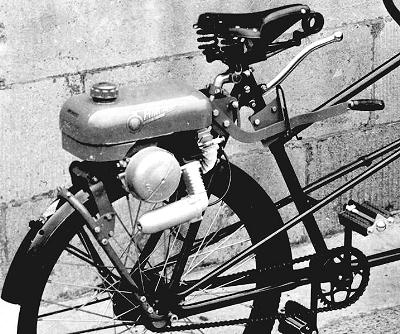
Mini-Motor MkIV
(detail taken from works photo)
As our club records of surviving machines show, production numbers ran approximately as follows:
| Dates* | Model | Engine number range of known survivors |
|---|---|---|
| 1949-1950 | MkI | A193 to A10396 |
| 1950-1951 | MkII | B10575 to B44278Z |
| 1951-1953 | MkIII | C44604 to C68919 |
| 1953-1955 | MkV | F70806 to F73741 |
| 1955-1957 | MkV | G74390Z to G74434Z, H74807Z |
| [* Date is first registration date, not date of manufacture] | ||
The suffix letter Z denotes that a Miller flywheel magneto was supplied as original equipment, rather than the alternative Wico-Pacy Bantamag. Engines with other prefix letters (e.g. "E") were industrial units.
| Number | Description | Number | Description |
|---|---|---|---|
| 4 | Crankshaft distance sleeve | 5 | Steel roller |
| 10 | Cylinder base gasket | 11 | Cylinder block |
| 13 | Little end bush | 14 | Gudgeon pin, std |
| 15 | Piston, std | 16 | Piston ring, std |
| 17 | Cylinder head | 19 | Inlet manifold gasket |
| 20 | Inlet manifold (early model) | 20A | Inlet manifold |
| 21 | Exhaust manifold gasket | 22 | Exhaust manifold |
| 23 | Exhaust silencer gasket | 24 | Exhaust silencer body |
| 25 | Exhaust silencer, perforated tube | 26 | Exhaust silencer, packing |
| 28 | Main bearing | 29 | Crankshaft seal, roller side |
| 30 | Roller Washer, 1/2" std flat | 31 | Roller Nut, 1/2" BSF |
| 32 | Washer, plain, 5/16" | 34 | Washer, plain, 1/4" |
| 35 | Screw, exhaust silencer, 1BA × 9/16" cheese head | 36 | Piston ring peg |
| 38 | Washer, spring, 1/4" | 39 | Cylinder base stud |
| 40 | Nut, 1/4" BSF | 41 | Manifold stud, 1/4" |
| 42 | 2BA x 9/16" cheese head screw | 43 | Washer, spring, 2BA |
| 44 | Roller guard screw, 1BA × 3/8" cheese head | 45 | Gudgeon pin circlip |
| 46 | Cylinder head stud | 47 | Sparking plug (Lodge C14) |
| 48 | Long stud, rear engine mounting, MkI | 49 | Roller washer, fibre |
| 50 | Crankshaft seal, magneto side | 51 | Tank pivot pinch bolt |
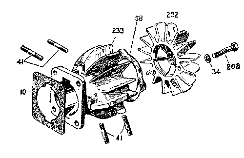
| 57 | Front mounting plate bolt | 58 | Cylinder head gasket |
| 59 | Drive control pinch bolt | 61 | Cable stop, early MkI drive control |
| 62 | Drive control roller (MkI) | 64 | Front mounting plate, short |
| 65 | Front mounting plate, long | 60 | Set screw |
| 68 | Saddle pillar attachment | 68 | Clip for saddle pillar attachment |
| 70 | Tank pivot block | 71 | Tank pivot bush |
| 74 | Tank pivot bolt | 75 | Drive control spring, early MkI |
| 78 | Cable adjuster, drive control | 81 | Nut 5/16" BSF |
| 85 | Spring washer, 1BA | 86 | Nut, decompressor, 2BA |
| 88 | Cable adjuster locknut, drive control, 1/4" BSF | 89 | Woodruffe key, 3/8" × 1/6" |
| 90 | Filler cap washer, cork or leather | 91 | Petrol tap washer, fibre |
| 92 | Flywheel washer, 5/16" spring | 93 | 2BA x 7/8" cheese head screw |
| 94 | Drive control roller washer, 2BA plain | 100 | Engine mounting spacer, fibre |
| 101 | Engine mounting washer, 21/64" fibre | 102 | Rear engine mounting washer, 17/32" fibre |
| 103 | Lower plate, top engine mounting | 106 | Trojan head transfer |
| 107 | Mini-Motor transfer | 108 | Box spanner, roller nut/plug |
| 109 | 1BA × 3/4" cheese head screw | 113 | Spring Washer |
| 114 | Circlip | 116A | Compression spring, carburettor pump plunger |
| 117 | Air cleaner stop | 119 | Carburettor fixing screw |
| 122 | Plug for carburettor pump | 123 | Mixing chamber cover |
| 124 | Carburettor fixing screw | 125 | Ring |
| 126 | Thottle guide screw | 130 | carburettor cover |
| 131 | Air filter screw | 132 | Throttle slide |
| 133 | Air cleaner cover | 124 | Air cleaner disc |
| 135 | Carburettor body | 138 | Carburettor pump piston |
| 139 | Main jet No 43 | 142 | Plug for filter elbow |
| 144 | Banjo union base washer | 145 | Main jet washer |
| 146 | Banjo union top washer | 147 | Air cleaner filter |
| 148 | Carburettor gasket | 148 | Carburettor pump base washer |
| 152 | Throttle cable adjusting screw | 153 | Carburettor sump screw |
| 154 | Carburettor sump washer | 155 | Cable abutment |
| 156 | Solderless nipple | 161 | Rear number plate (MkI to Mk III) |
| 165 | Body, drive control lever, 1st type | 166 | Lever, drive control lever, 1st type |
| 167 | Trigger, drive control lever, 1st type | 168 | Handlebar clamp, drive control lever, 1st type |
| 169 | Trigger spring, drive control lever, 1st type | 170 | Cable outer stop, drive control lever, 1st type |
| 171 | Trigger pivot, drive control lever, 1st type | 172 | Clamp nut, drive control lever, 1st type |
| 173 | Clamp bolt, drive control lever, 1st type | 174 | Pivot bolt, drive control lever, 1st type |
| 175 | Pivot nut, drive control lever, 1st type | 176 | Spring washer, drive control lever, 1st type |
| 177 | Drive control cable outer | 178 | Drive control cable inner |
| 179 | Cable ferrule, drive control | 181 | Barrel nipple, drive control |
| 182 | Tube nipple (fixed), drive control | 185 | Body, throttle lever |
| 186 | Lever, throttle lever | 187 | Top plate, throttle lever |
| 188 | Handlebar clamp, throttle lever | 189 | Small washer, throttle lever |
| 190 | Large washer, throttle lever | 191 | Spring washer, throttle lever |
| 192 | Central bolt, throttle lever | 193 | Handlebar clamp bolts, throttle lever |
| 194 | Throttle cable outer | 195 | Throttle cable inner |
| 196 | Cable ferrule, throttle | 197 | Barrel nipple, throttle |
| 198 | Tube nipple, throttle | 206 | Washer |
| 207 | End stop, early MkI drive control | 208 | Cylinder head bolt |
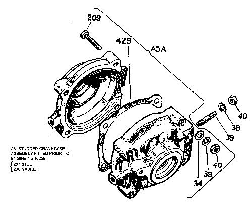
| 209 | Crankcase bolt | 210 | Front mounting arm |
| 211 | Front mounting clamp | 212 | Rear engine mounting nut, 5/16" BSF |
| 218 | Front mounting bolt | 214 | Hub bolt |
| 215 | Hub screw | 219 | Special washer |
| 220 | Special washer | 221 | Locking washer, top engine mounting |
| 222 | Setscrew, top engine mounting | 232 | Cylinder head |
| 233 | Cylinder | 234 | Roller spanner |
| 235 | Drive control roller nut, 2BA | 236 | Crankcase gasket (studded type) |
| 237 | Crankcase stud | 239 | Engine mounting washer, plain |
| 240 | Side plate | 241 | Washer |
| 242 | Bolt | 243 | Drive control bracket bolt, MkIII |
| 244 | Filter holder | 245 | Filter gauze |
| 246 | Filter spring | 247 | Sediment plug for carburettor |
| 250 | Gudgeon pin, oversize 9/16" (14.288mm) | 251 | Piston, +.020" |
| 252 | Piston, +.040" | 253 | Piston ring, +.020" |
| 254 | Piston ring, +.040" | 256 | Washer for sediment plug |
| 257 | Thrust collar | 258 | 5/16" Thackeray spring washer |
| 259 | Cable stop, later MkI drive control | 260 | Drive control spring, later MkI |
| 261 | Retaining plate, later MkI drive control | 262 | Thrust washer, later MkI drive control |
| 263 | End stop, later MkI drive control | 265 | Lever, drive control, 2nd type |
| 266 | Trigger, drive control lever, 2nd type | 268 | Cable inner stop, drive ctl lever 2nd type (screw nipple) |
| 269 | Screwed nipple outer, drive control | 270 | Screwed nipple inner, drive control |
| 271 | Handlebar clamp, drive control lever, 2nd type | 272 | Trigger bush, drive control lever, 2nd type |
| 273 | Pivot bolt, drive control lever, 2nd type | 274 | 2BA plated nut, drive control lever, 2nd type |
| 275 | Bolt, drive control lever, 2nd type | 277 | Trigger spring, drive control lever, 2nd type |
| 278 | Cable outer stop, drive control lever, 3rd type | 279 | Decompressor body |
| 280 | Decompressor valve | 281 | Decompressor cable stop |
| 282 | Decompressor spring | 294 | Main jet, size 39 |
| 295 | Main jet, size 40 | 296 | Main jet, size 41 |
| 297 | Main jet, size 42 | 298 | Main jet, size 44 |
| 299 | Main jet, size 45 | 300 | Main jet, size 46 |
| 301 | Main jet, size 47 | 302 | Coil & core group (Wico) |
| 303 | Coil core fixing screw (Wico) | 304 | Coil core fixing screw lock washer (Wico) |
| 305 | Condenser (Wico) | 306 | Condenser screw (Wico) |
| 307 | Condenser fixing screw (Wico) | 308 | Condenser fixing screw lock washer (Wico) |
| 309 | Breaker arm pivot & fixing plate (Wico) | 310 | Cam pad bracket (Wico) |
| 311 | Cam pad (Wico) | 312 | Cam pad bracket fixing screw(Wico) |
| 313 | Cam pad bracket fixing screw lock washer (Wico) | 314 | Contact breaker, fixed (Wico) |
| 315 | Eccentric screw (Wico) | 316 | Fixed contact screw (Wico) |
| 317 | Fixed contact lock washer (Wico) | 318 | Fixed contact screw washer (Wico) |
| 319 | Contact breaker, sprung (Wico) | 320 | Breaker arm spring clamp plate (Wico) |
| 322 | Breaker arm spring clamp lock washer (Wico) | 323 | Breaker arm spring washer (Wico) |
| 324 | Flywheel (Wico) | 325 | Magneto cover (Wico) |
| 326 | Magneto cover clip (Wico) | 327 | HT Pick-up (Wico) |
| 328 | HT terminal block gasket (Wico) | 329 | HT fixing screw (Wico) |
| 330 | HT terminal fixing screw lock washer (Wico) | 331 | HT terminal block contact (Wico) |
| 332 | HT terminal end (Wico) | 333 | Rubber dust cover (Wico) |
| 335 | HT wire terminal end (Wico) | 341 | Stator plate (Wico) |
| 353 | Drive control guide rod, later MkI on | 354 | HT lead terminal cover screw (Miller) |
| 355 | HT terminal cover (Miller) | 356 | Terminal cover rubber grommet (Miller) |
| 357 | Contact breaker arm terminal screw (Miller) | 358 | Shakeproof washer for contact breaker arm screw (Miller) |
| 359 | Plain washer for contact breaker arm screw (Miller) | 360 | Contact breaker unit (Miller) |
| 361 | Condenser (Miller) | 362 | Shakeproof washer for condenser (Miller) |
| 363 | Magneto cover (Miller) | 364 | HT coil (Miller) |
| 365 | Cam oiler (Miller) | 366 | Backplate (Miller) |
| 367 | 2 fixing screws & washers (Miller) | 368 | Insulating washer (Miller) |
| 381 | Drive control sector plate, later MkI | 382 | Hoop, later MkI |
| 383 | Hoop spacer, intermediate/later MkI | 384 | Csk bolt for hoop |
| 396 | Special silencer baffle | 397 | RH hoop endplate, intermediate/later MkI |
| 398 | LH hoop endplate, intermediate/later MkI | 399 | Drive control bolt |
| 413 | Piston .0025" oversize, with gudgeon pin | 414 | Circlip |
| 415 | Piston ring .0025" oversize | 420 | Cable outer stop (solid nipple), drive ctl lever 2nd type |
| 426 | 1BA Csk bolt, later roller guard | 429 | Crankcase gasket (nut & bolt type) |
| 430 | Lever, drive control lever, 3rd type (Amal) | 431 | Body, drive control lever, 3rd type (Amal) |
| 432 | Handlebar clamp, drive control lever, 3rd type (Amal) | 433 | Trigger, drive control lever, 3rd type (Amal) |
| 434 | Trigger spring, drive control lever, 3rd type (Amal) | 435 | Rivet, drive control lever, 3rd type (Amal) |
| 436 | Pivot bolt, drive control lever, 3rd type (Amal) | 437 | Nut, drive control lever, 3rd type (Amal) |
| 438 | Handlebar clamp bolt, drive control lever, 3rd type (Amal) | 451 | Terminal for Lodge sparking plug |
| 452 | Tank pivot grease nipple | 453 | Tank pivot block, later type |
| 454 | Tank pivot plate, later type | 456 | Sparking plug, Champion J8 |
| 458 | Copper/asbestos washer decompressor | 459 | Strengthening piece |
| 467 | 1/16" × 1" split pin, MkII drive control | 470 | Body, throttle/decompressor control |
| 471 | Lever, throttle/decompressor control | 472 | Top plate, throttle/decompressor control |
| 473 | Cable drum, throttle/decompressor control | 474 | Spring washer, throttle/decompressor control |
| 475 | Fibre washer, throttle/decompressor control | 476 | Plain washer, throttle/decompressor control |
| 477 | Cable adjuster, throttle/decompressor | 478 | Cable adjuster nut, throttle/decompressor |
| 479 | Throttle cable outer (decompressor model) | 484 | Thrust washer, MkII-on drive control |
| 487 | Upper pin, MkII-on drive control | 488 | Lower pivot stud, MkII-on drive control |
| 489 | Return spring | 491 | Cable end stop, MkII drive control |
| 492 | Middle pin, MkII drive control | 498 | Decompressor cable inner |
| 499 | Decompressor cable outer | 500 | Eyelet nipple, decompressor |
| 503 | Decompressor cable retaining screw | 504 | Short stud, MkII rear engine mounting |
| 515 | 5/16" BSF Simmonds nut for drive control bracket, MkIII | 516 | Decompressor cover |
| 521 | Roller disc | 522 | Air cleaner gauze |
| 523 | 1BA Shakeproof washer, roller guard | 542 | 47mm × 17mm × 14mm ball bearing (MkV roller side) |
| 543 | Distance piece | 562 | Spacer washer |
| 563 | Piston, +.010" | 564 | Piston ring, +.010" |
| 565 | Piston, +.030" | 566 | Piston ring, +.030" |
| 567 | Dust guard, roller side MkV | 598 | Crankcase bolt, MkIII on |
| 638 | Front mounting stud, MkIII | 640 | Link plate, MkIII drive control lever |
| 641 | Inner cable stop, MkIII drive control lever | 642 | Top plate, MkIII drive control lever |
| 643 | Bottom plate, MkIII drive control lever | 645 | Bush, MkIII drive control lever |
| 646 | Lever, MkIII drive control lever | 647 | Pivot bolt, MkIII drive control lever |
| 652 | Pivot screw, MkIII drive control lever | 664 | Sparking plug cap |
| 667 | RH number plate bracket, MkV | 668 | LH number plate bracket, MkV |
| 671 | Spacer for number plate bracket, MkV | 678 | Seat pillar clamp half, MkV |
| 679 | Pivot block, MkV | 680 | Seat pillar clamp plate, MkV |
| 681 | Pivot block clamp plate, MkV | 40017 | Sub-frame spacer, MkV |
| 40080 | ¼" BSF bolt, MkV rear number plate | A3 | Piston assy, std |
| A5 | Crankcase Assy (studded, engine < 15258) | A5A | Crankcase Assy (nut & bolt type, engine => 15258) |
| A6 | Crankshaft/connecting rod assy | A7 | Exhaust assy |
| A8 | Wico-Pacy Bantamag | A9 | Carburettor |
| A10 | Roller guard | A12 | Carburettor jet holder |
| A13 | Carburettor pump knob and spindle | A14 | Petrol filter |
| A17 | Float and needle | A21 | Tank, MkI |
| A22 | Rear hoop assy, early MkI | A24 | Petrol tap |
| A25 | Petrol pipe | A26 | HT lead (Wico) |
| A27 | Drive control lever, 1st type | A28 | Throttle lever, complete |
| A32 | Licence holder | A33 | Horn |
| A34 | Speedometer head | A35 | Speedometer cable |
| A36 | Drive control cable, MkI, 1st & 3rd type | A37 | Throttle cable (no decompressor) |
| A38 | Front & rear number plates | A40 | Front number plate |
| A41 | Magneto withdrawal tool | A42 | Filler Cap, early MkI |
| A47 | Front mounting assy | A48 | Special attachment plate assy |
| A49 | Tap filter assy | A50 | Petrol tap and filter |
| A54 | Drive control lever, complete, 2nd type (Trojan) | A55 | Drive control cable, MkI, 2nd type, fixed nipple |
| A56 | Decompressor assy | A57 | Fuel tank, MkV |
| A59 | Drive control cable for tandems | A60 | Throttle cable for tandems (no decompressor) |
| A62 | Miller magneto | A63 | Filler Cap, later MkI onwards |
| A64 | Hoop with fixed sector, intermediate MkI | A65 | Hoop assy, intermediate MkI |
| MA65 | Hoop assy, last MkI (with guide rod) | A66 | HT lead (Miller) |
| A68 | Stator plate unit (Wico) | A69 | Stator plate with coil & core only (Wico) |
| A70 | Drive control cable for tandems | A71 | Spanner set |
| A74 | Piston assy, +.020" | A75 | Piston assy, +.040" |
| A76 | Piston assy, +.0025" | A77 | Body, drive control lever, 2nd type (Trojan) |
| A87 | Drive control lever, complete, 3rd type (Amal) | A95 | Spare parts price list |
| A96 | Cycle unit instruction book | A97 | Flywheel (Miller) |
| A98 | Back plate & all parts (Miller) | A99 | Contact breaker assy (Miller) |
| A100 | Front tank pivot assy, later type | A101 | Contact breaker assy (Wico) |
| A103 | Throttle/decompressor control, complete | A104 | Throttle cable (decompressor models) |
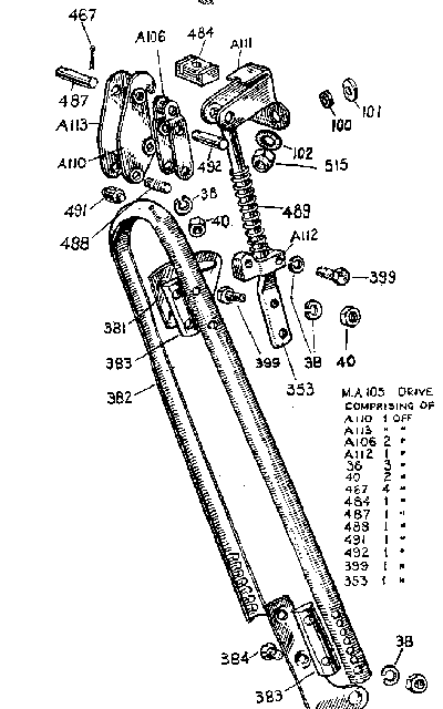
| A105 | Drive control assy, MkII on (except guide rod & spring) | MA105 | Drive control assy, MkII on (including guide rod & spring) |
| A106 | Lower scissor arm, MkII drive control | A108 | Drive control cable, MkII |
| A109 | Drive control cable for tandems, MkII | A110 | RH upper scissor arm, MkII drive control |
| A111 | Upper bracket, MkII drive control | A112 | Lower pivot block, MkII drive control |
| A113 | RH upper scissor arm, MkII drive control | A114 | Throttle cable for tandems (decompressor models) |
| A115 | Decompressor cable | A115 | Decompressor cable for tandems |
| A119 | Drive operating cable, MkII conversion & Amal lever | A120 | Drive operating cable for tandems, MkII conversion & Amal lever |
| A121 | Carrier | A123 | Carborundum Roller |
| A124 | Hoop assy, MkV (including guide rod) | MA124 | Hoop assy, MkII (no guide rod) |
| A125 | Crankcase assy | A128 | Crankcase halves assy, MkIII on |
| A134 | Piston assy, +.010" | A137 | Piston assy, +.030" |
| A145 | Drive control upper bracket, MkIII on | A147 | Tank, MkIII |
| A154 | Drive control lever, complete, MkIII on | A155 | Body, MkIII drive control lever |
| A161 | Herringbone drive roller | A163 | Roller spanner (for herringbone type) |
| A165 | Rear number plate (MkV) | A170 | Engine mounting subframe, MkV |
| A9005 | Fuel pipe | K102 | Decarbonising gasket set |
| K103 | Engine overhaul gasket set | K104 | Magneto spares kit (Wico) |
| K105 | Nut grips | K106 | Set of dealers' service tools |
| K107 | Drive control mechanism kit (Trojan lever) | K108 | Drive control mechanism kit (Amal lever) |
| K109 | Decompressor valve & controls with service cyl head | K110 | Decompressor valve & controls for plugged cyl head |
Equipped with this unit, your bicycle will be transformed into the simplest motor vehicle on the road, yet it will retain all the advantages of a bicycle.
The engine itself is constructed of a few sturdy parts and requires little attention. It is, nevertheless, important that it be fitted with care, preferably by a mechanic or cycle dealer. Alternatively, by following the instructions given in this book the work may be carried out by anyone with ordinary mechanical aptitude.
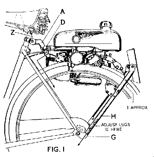
To increase the pressure of the roller on the tyre; move the
hinge "D" in the direction of the arrow for a small increase, or
the
U-shaped fork "H" for larger increases.
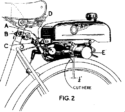
In order to obtain good results from the engine, it is very important that the pressure exerted by the roller on the tyre is adequate to obtain a positive drive.
If the engine tends to race when you open the speed control lever abruptly, then the pressure of the roller on the tyre should be increased, this will avoid slip of the roller on the tyre with consequential increase in rate of tyre wear.
To increase the pressure of the roller on the tyre, first check to ensure that the tyre is inflated hard. If slip still occurs, slacken the nuts "C" on the hinge "D" and slide the hinge downwards in the direction of the arrow, Fig.1. Then re-tighten the nuts "C." If a large amount of adjustment is required, the U-shaped stay should be moved down another notch at "G," Fig.1.
The unit runs on a mixture of petrol (or gasoline) and oil. First quality lubricant is required and the best results are obtained from the use of "Colloidal Filtrate Oil". If this oil is not available, a known brand of grade SAE.20 oil should be employed.
The proportions of the mixture of petrol (or gasoline) and oil are 20 to 1 and can be mixed as follows:
3 measures of oil to 1 gallon of petrol.
The correct measure will be found within the underside of the tank filler cap.
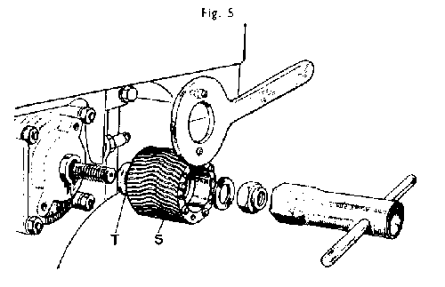
It is better to mix in petrol with the oil in a separate container before pouring into the fuel tank, but when this cannot be done it is important to operate in the following order:
Having turned on the petrol tap. depress the primer plunger "U" on the carburettor (Fig.6.) four or five times; place the mixture control in the "RICH" position (if this is the first time you have started the unit). Grasp and pull into the ratchet stop the drive control lever (long lever on left-hand side of handlebar) bringing the roller into contact with the tyre. Move the speed control lever (small lever on the right-hand side of handle-bar) to the right. thus opening the decompressor valve; mount the bicycle and pedal away. The engine will now be revolved, but will not commence firing. When speed has been gathered, move the speed control lever smartly towards the left, thereby closing the decompressor valve and opening the throttle halfway. The engine should now commence firing. Continue to pedal briskly until the engine is running smoothly, then your speed may be regulated by operation of the speed control lever.
If you wish to use the machine as an ordinary bicycle, lift the roller from the tyre by operating the drive control lever on the left-hand side of the handlebar. BUT REMEMBER TO STOP THE ENGINE BY SHUTTING DOWN THE SPEED CONTROL LEVER.
During the first four-hundred miles do not put too much strain on the engine. If the engine tends to slow down under effort open decompressor valve, by means of the control lever. and pedal for a short while until the engine has cooled down.
IF YOU HAVE OBSERVED THESE INSTRUCTIONS DURING, THE RUNNING-IN PERIOD YOU CAN THEN USE YOUR MINI-MOTOR WITHOUT ANY SPECIAL PRECAUTION AFTERWARDS.
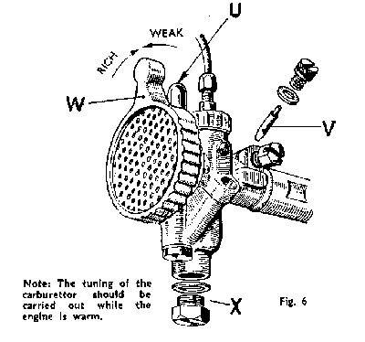
Adjustments to the mixture may be required to suit varying climates. For cold climates a richer setting of the carburettor is obtained by substituting the existing jet "V" (Fig.6.) by a bigger jet. The size of the jet is marked on the outside. If only a minor adjustment is needed, as, for instance, when changing from Summer to Winter conditions, it can be obtained by turning the air intake "W" in the direction of the arrow marked "Rich."
A weaker mixture may be needed in a warmer climate and is obtained either by substituting the existing jet by a smaller one, or again for a minor adjustment, by turning the air intake in the direction of the arrow marked "weak."
Too rich a mixture is indicated by a pronounced tendency for the engine to four-stroke at slow speeds, or even with an extremely rich mixture at full throttle. (A two-stroke engine, such as the Mini-motor, is said to "four-stroke" when the exhaust note becomes staccato and uneven.)
Running on too rich a mixture fouls the insulator around the central electrode of the sparking plug which may result in its becoming unserviceable.
Too weak a mixture is indicated by a tendency to run erratically at full throttle (the exhaust note undulates) or, by poor pulling and the fact that the highest speed is not obtainable at the full throttle opening, but with a somewhat smaller opening of the speed control lever.
It is advisable that all adjustments to the magneto be carried out either by a Mini-Motor Agent or by a similarly experienced mechanic, and it is to such as these that the following paragraphs are addressed.
EVERY 1,000 MILES
EVERY 2,000 MILES
NOTE. - We do not normally recommend removing the cylinder barrel when decarbonising the engine, but if it does become necessary to remove the barrel, be sure that two spare piston rings are available against possible breakage, also that new cylinder base and cylinder head gaskets are to hand for use when rebuilding the engine.
IF THE ENGINE STOPS OR WILL NOT START
The following checks should be made In succession:
SHOULD YOUR ENGINE RUN BADLY
SHOULD YOUR MINI-MOTOR "SLIP"
The first symptom of roller slip, if and when it does occur, is of the engine going at top speed while the cycle and rider proceed comparatively slowly. As roller slip can result in reduced tyre life, the following points should be examined at once.
Check rear tyre pressure. It should be hard but not "solid" (i.e., 30 to 40 lb. per square inch).
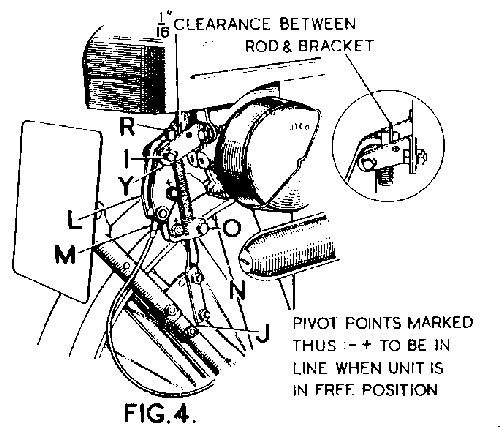
Adjust the drive cable to take up slack. See that it moves freely, that it is well oiled at each end, and that there are no acute bends; the cable should have a wide sweep as it enters the toggle assembly (Fig.4.). Unlock the toggle action by moving the handlebar lever slightly and then press down firmly on the petrol tank to ensure that the Mini-Motor is pivoting freely; if it is not, the forward hinge lug should be dismantled and lubricated.
With the Mini-Motor in the "off" position, make certain that the gap between roller and tyre is not more than 1/8 in. If the gap is greater, the unit should be adjusted as described earlier. Properly adjusted, the "Sure-grip" roller is capable of transmitting the full drive of the Mini-Motor in almost any weather condition.
Parts of this article first appeared in Buzzing magazine in December 1990. It has been extensively modified since then